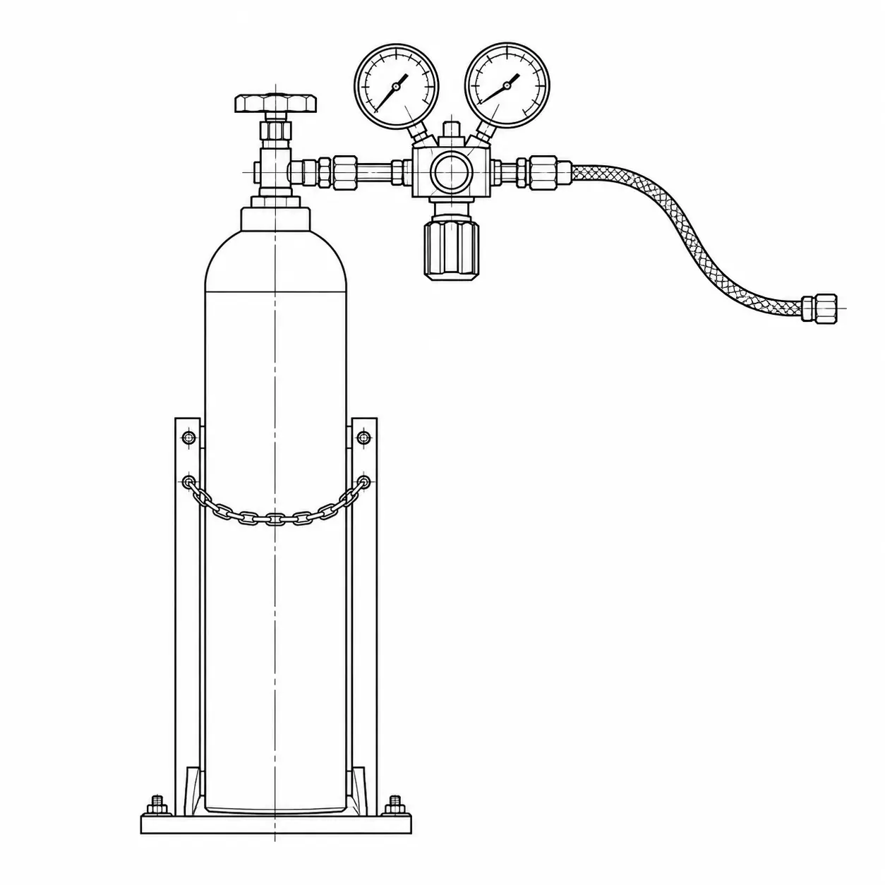
Single cylinder
One cylinder feeding a small demand.
Industrial gas & cryogenic engineering
PES designs, selects, fabricates, installs and commissions gas-handling systems around the gas service, source conditions, required delivery pressure, flow, point-of-use demand and installation environment.
Gas moves from a stored or generated source through a connection, primary pressure control, a distribution header, branch isolation and, where specified, a point-of-use regulator before it reaches process equipment. Primary control is usually near the source. Point-of-use control is local to the application.
Drawing — Source to use
Source → process
01
Cylinder, bank, bundle or cryogenic storage.
Cylinders, bulk connection, tank isolation.
Cryogenic equipment02
Interface between the stored gas and the first control hardware.
Pigtails, hoses, inlet valves.
Connectors03
First reduction from source pressure toward a usable distribution pressure.
Manifold, regulator, gauges, isolation.
Gas regulators04
Header that carries gas through the building or process area.
Pipe or tube, supports, fittings.
Pipeline installation05
Local isolation of a take-off from the header.
Branch valves and identification.
Valves & flow control06
Final pressure adjustment close to the consuming equipment.
Regulator, local gauge, outlet isolation.
Pressure control07
Machine, instrument, torch or process that consumes the gas.
Equipment interface and commissioning.
Engineering processFig. 02 — Conceptual system architecture. Final component selection and arrangement depend on the gas, operating conditions, application, site and applicable requirements.
One cylinder feeding a small demand.
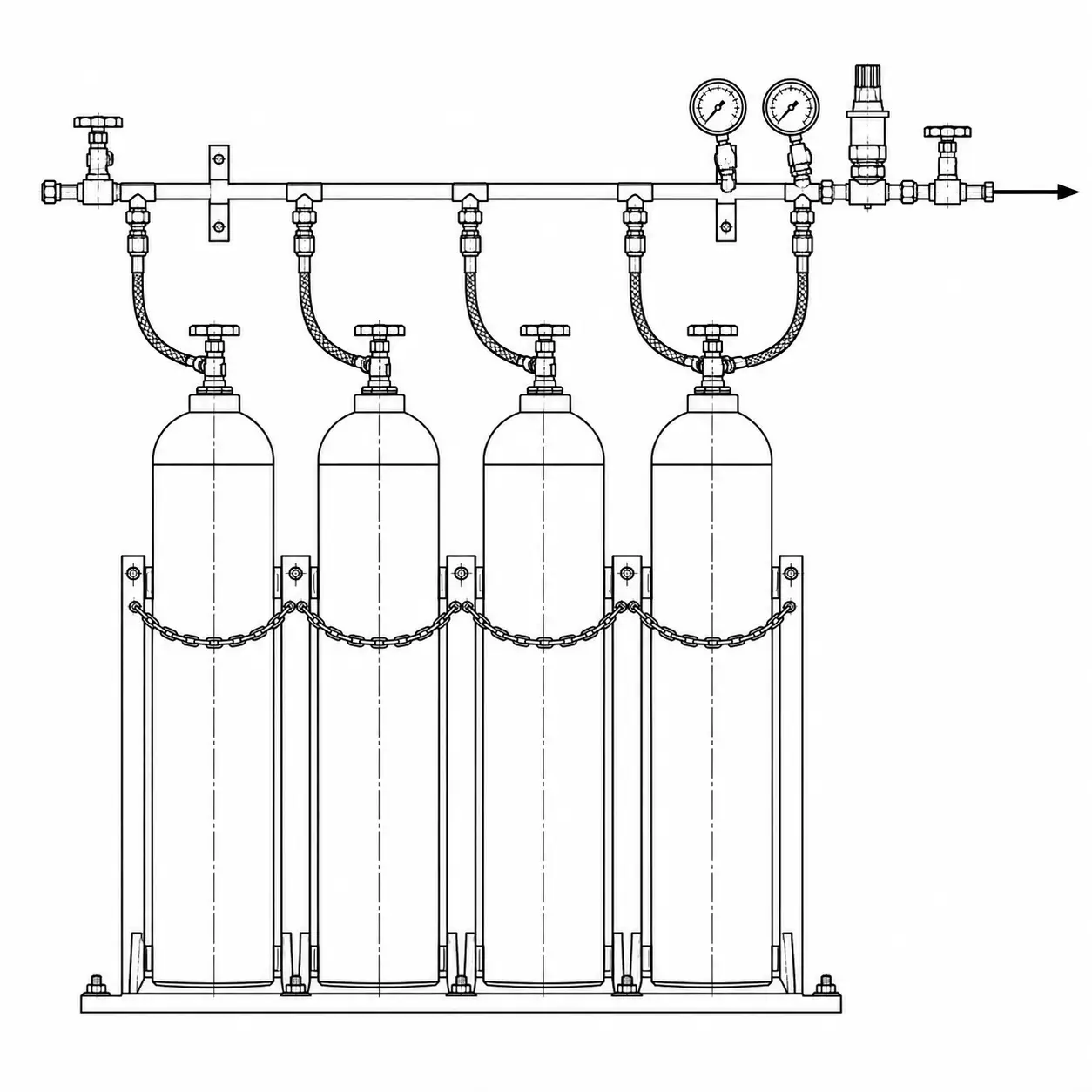
Several cylinders on a common header.
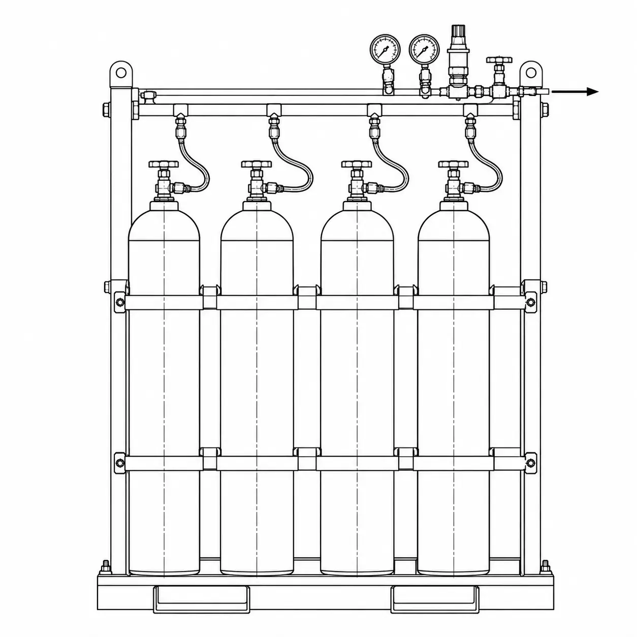
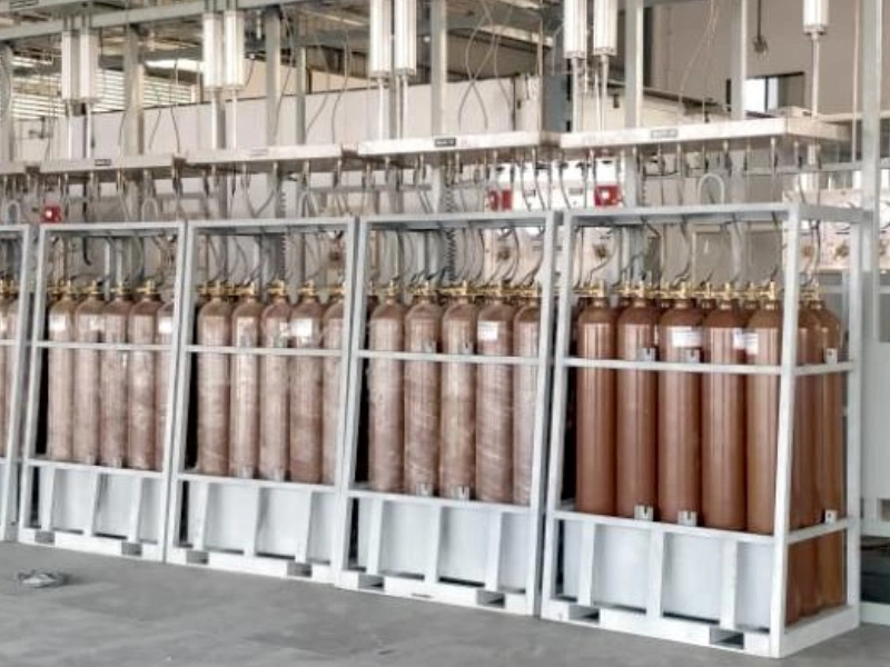
Packaged multi-cylinder source.
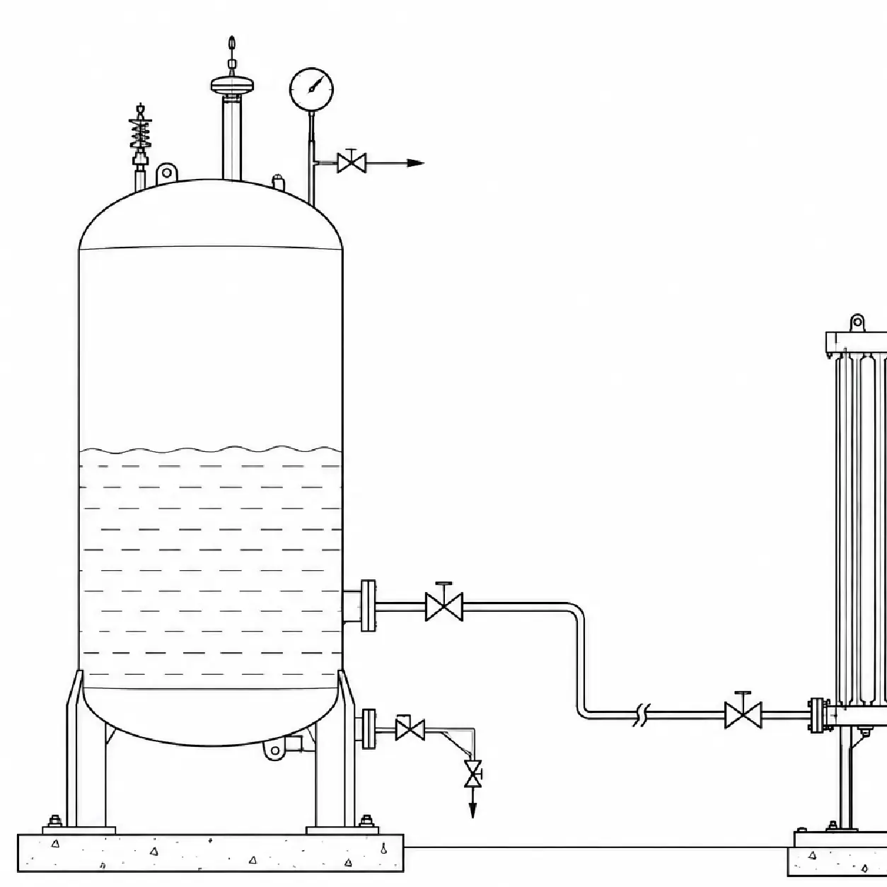
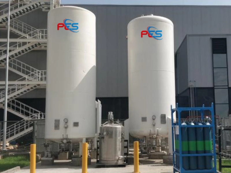
Liquid storage with vaporization downstream.
These drawings illustrate general system concepts and are not fabrication, installation or construction drawings. Final system design, component selection, materials, ratings and protective provisions must be established for the specific gas service, operating conditions, application, site and applicable requirements.
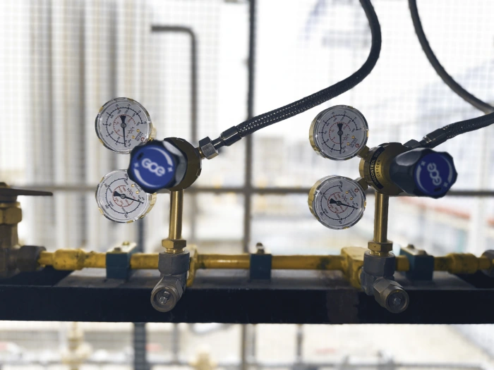
A representative panel combines inlet isolation, pressure indication, a regulator and outlet isolation so that primary pressure reduction, isolation and controlled downstream delivery can be operated and maintained from one assembly. Accessibility for gauges, adjustment and isolation is part of the layout, not an afterthought.
Drawing — Panel anatomy
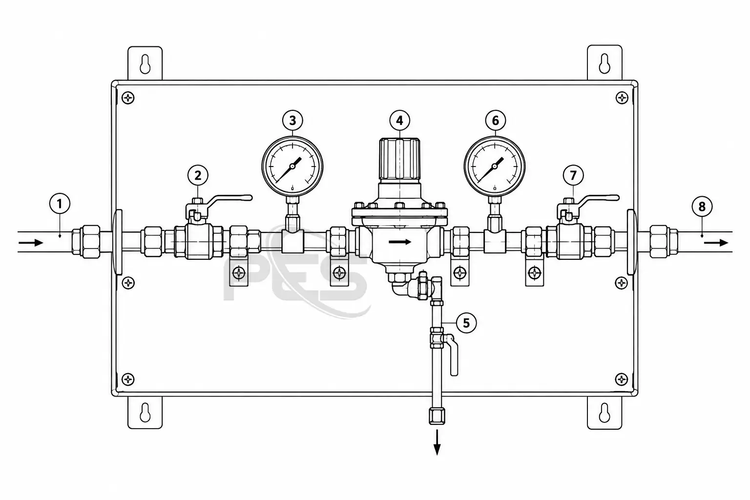
Fig. 03 — Representative pressure-control arrangement. Components and flow path vary by application.
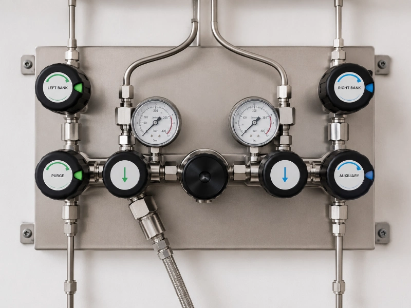
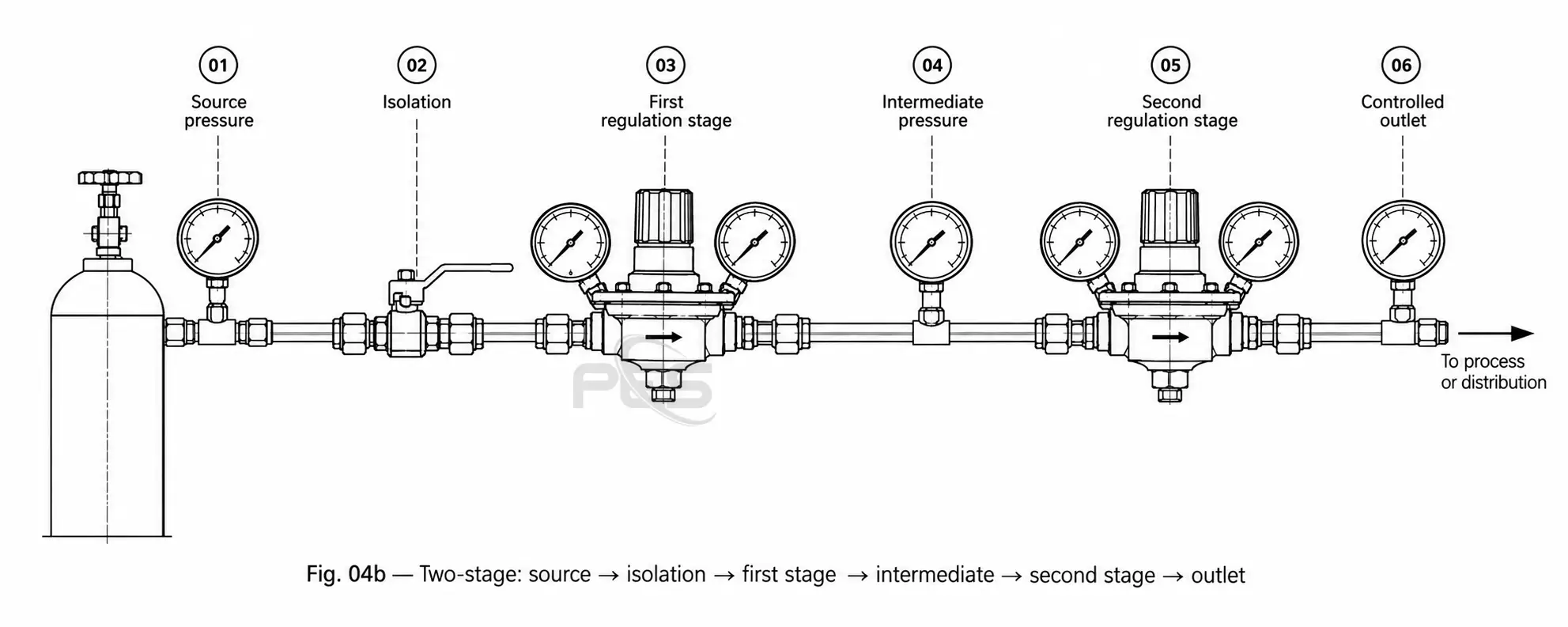
Selection depends on gas, inlet variation, required outlet condition, flow and how much outlet-pressure stability the process needs. One configuration is not always better. Both arrangements require engineering review.
Drawing — Regulation stages
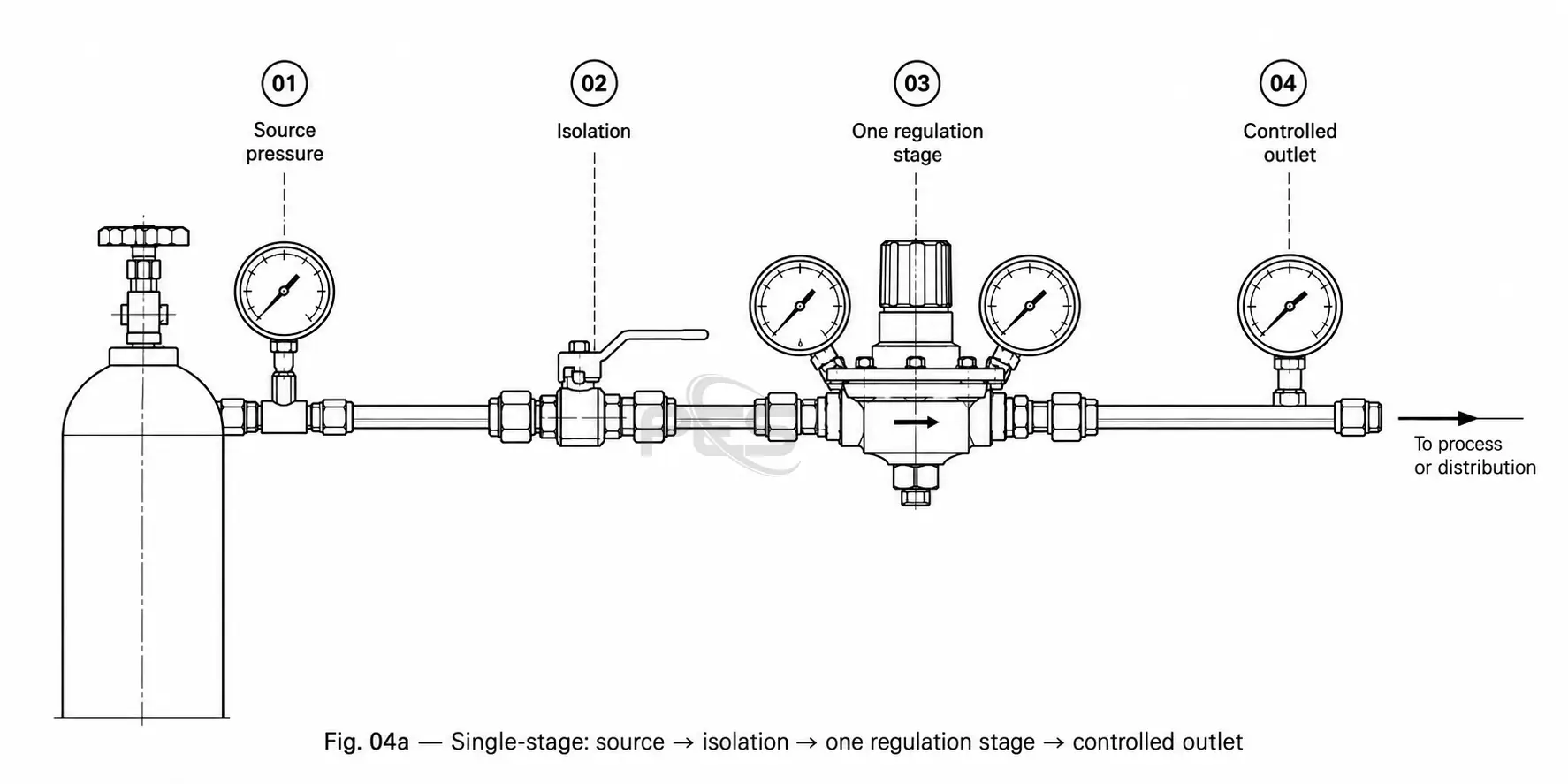
| Topic | Single-stage | Two-stage |
|---|---|---|
| Pressure-reduction arrangement | One primary regulation stage after isolation. | Two successive regulation stages with an intermediate condition. |
| Outlet stability considerations | Outlet condition may be more influenced by inlet and demand changes. | May be considered where more stable outlet pressure under changing inlet conditions is important. |
| Inlet-pressure variation | Cylinder depletion or source swing can show at the outlet. | The first stage can reduce the influence of source-pressure change on the second stage. |
| Adjustment requirements | Typically one set-point to maintain. | Two stages to set and to understand during operation. |
| System complexity | Fewer components and a simpler station. | More components, more connections and more documentation. |
| Possible applications | May suit many industrial, utility and general distribution duties after engineering review. | May be considered for high-purity, laboratory or critical process duties after engineering review. |
| Maintenance considerations | Fewer joints and instruments to inspect. | Additional stages, gauges and joints to inspect and maintain. |
Related: Single Stage Gas Regulator · Double Stage Gas Regulator
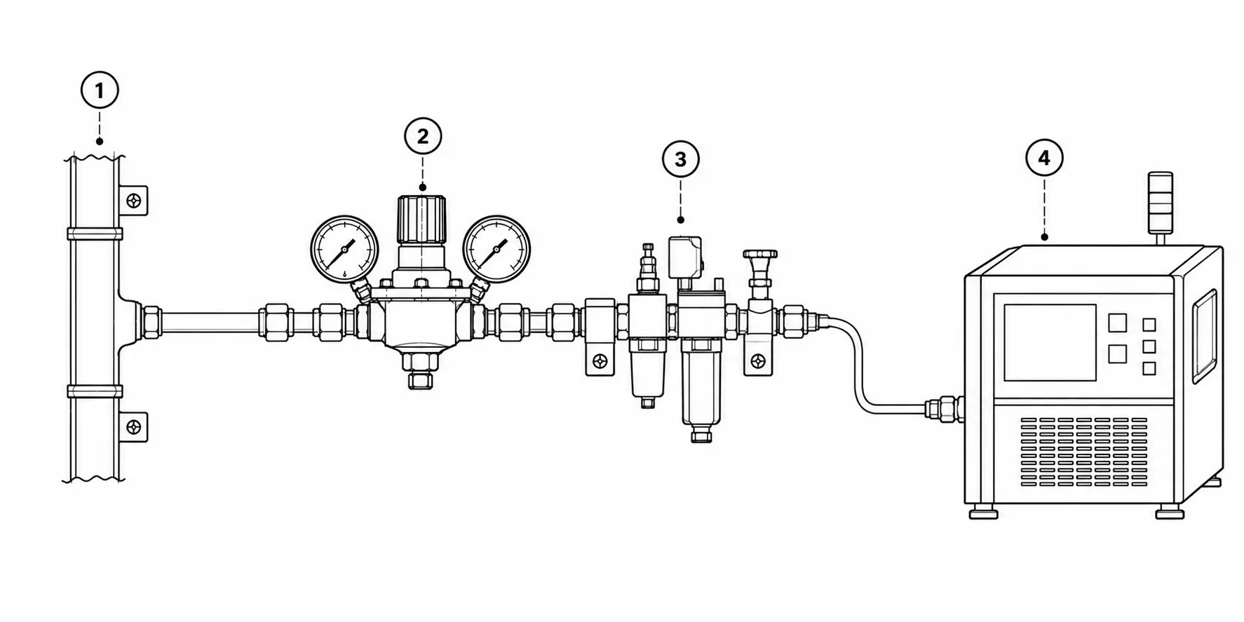
Point-of-use regulation provides the final stage of pressure control close to the machine, instrument, test bench or process consuming the gas. It allows delivery pressure to be configured around the requirement of an individual application after gas has entered the distribution system. It is not required for every system.
Drawing — Point-of-use path
Distribution header
Branch isolation
Point-of-use regulator
Local pressure indication
Outlet isolation
Process equipment
Drawing — Point-of-use station
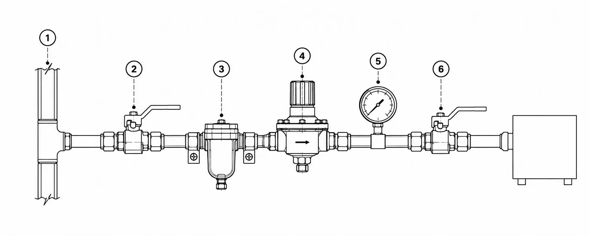
Fig. 05 — Representative point-of-use pressure-control arrangement. Component sequence, materials, connections and instrumentation depend on the gas service and application.
Central regulation only
Source → primary regulator → low-pressure distribution → equipment.
Central plus point-of-use
Source → primary pressure control → intermediate distribution → point-of-use regulator → equipment.
| Topic | Central only | Central plus point-of-use |
|---|---|---|
| System arrangement | Source → primary regulator → low-pressure distribution → equipment. | Source → primary pressure control → intermediate distribution → point-of-use regulator → equipment. |
| Pressure adjustment location | Mainly at the source or plant-level station. | Final adjustment at the branch or machine. |
| Multiple pressure requirements | All equipment sees the same distributed pressure unless further control is added. | Different branches can be set independently after engineering review. |
| Local pressure indication | May be limited to the primary station. | Can be provided at each use point where specified. |
| Isolation | Plant-level isolation; local isolation depends on the header design. | Local isolation can be provided with the point-of-use station. |
| Future equipment changes | A new pressure requirement may need a header change. | A new branch regulator may be added if the header capacity allows. |
| Engineering considerations | Simpler distribution; less local hardware. | More stations, more joints and more documentation. |
Related: Line regulators · Pressure control
Generic outlines only. The same arrangement is not implied for all gases. Materials, filters, protection and connections follow the gas service and application.
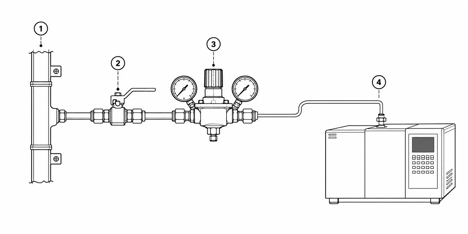
Distribution header → branch isolation → point-of-use regulator → instrument.
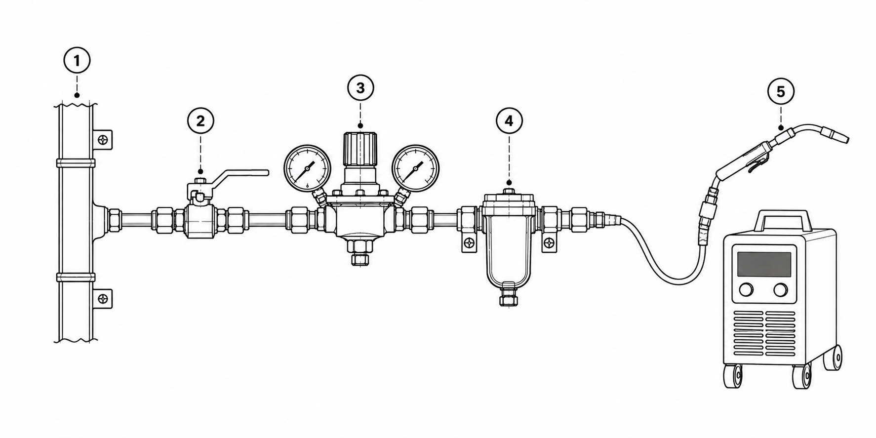
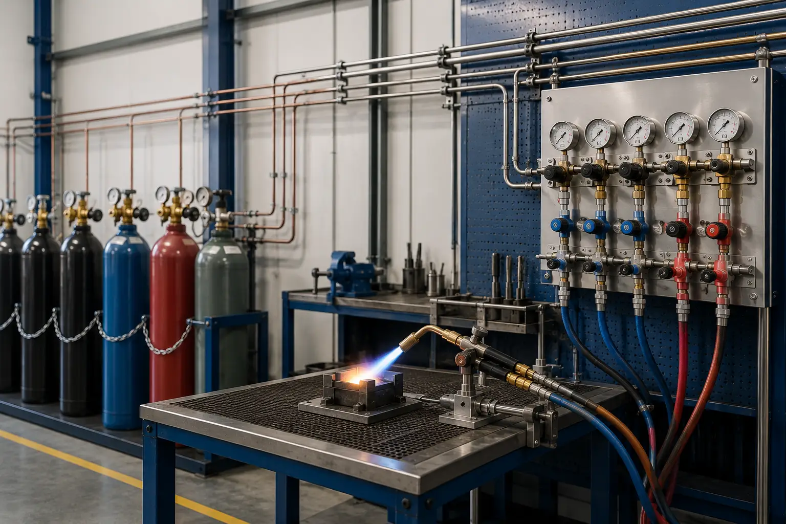
Distribution header → local isolation → point-of-use regulator → application-specific downstream protection → machine or torch.
Distribution header → point-of-use regulator → control assembly → process equipment.
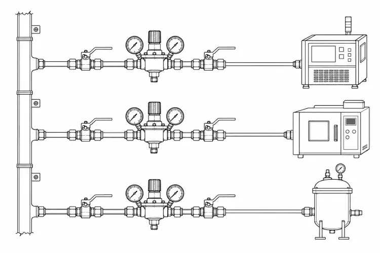
Common header → regulator A → equipment A; regulator B → equipment B; regulator C → equipment C.
Manifold selection follows source capacity, cylinder-change procedure, whether continuity of supply is required, whether changeover is manual or automatic, and how maintenance access is arranged.
Drawing — Manifold configurations
Cylinders on one header with isolation, non-return protection where applicable, and an outlet toward pressure control. Cylinder change is a planned interruption unless another source is available.
Cylinders · pigtails · header · isolation · non-return where applicable · pressure control · outlet
Two banks feed a common outlet. An operator selects the duty bank and changes the depleted bank while the other remains available, subject to the procedure.
Cylinders · pigtails · header · isolation · non-return where applicable · pressure control · outlet
A changeover device switches from the duty bank toward the reserve bank as inlet pressure falls. Continuity still depends on the configuration, set points and how the reserve is managed.
Cylinders · pigtails · header · isolation · non-return where applicable · pressure control · outlet
Fig. 07 — Simplified manifold concepts. Cylinders, pigtails, headers, isolation, non-return protection where applicable, pressure control and outlet to distribution are selected per project. Uninterrupted supply is not implied unless the configuration and operating procedure support it.
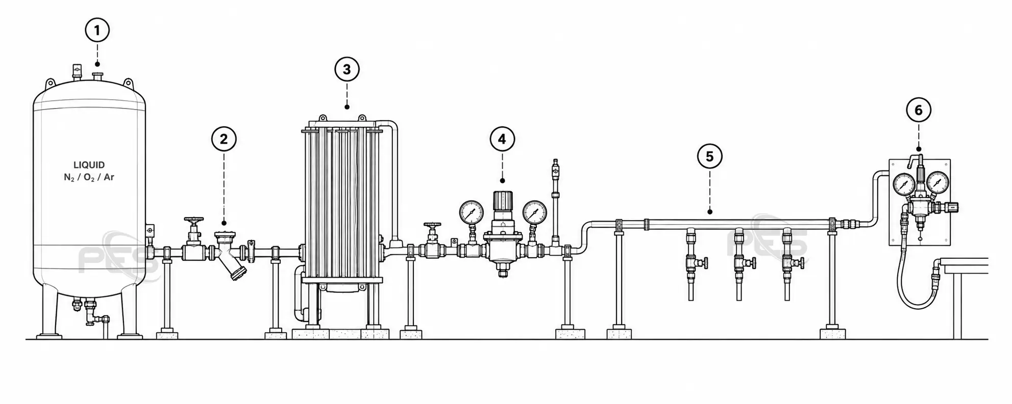
Where the source is a liquid-storage vessel, the path typically includes isolation and transfer, vaporization, pressure control, distribution and point of use. The arrangement depends on fluid, storage type, normal and peak flow, pressure, ambient conditions, operating conditions, redundancy and site layout.
Drawing — Cryogenic supply
Cryogenic storage
Isolation and transfer
Vaporization
Pressure control
Distribution
Point of use
Fig. 08 — Conceptual cryogenic path. Arrangement depends on fluid, storage type, normal and peak flow, pressure, ambient and operating conditions, redundancy and site layout. Tank capacities, vaporizer ratings and operating pressures are not stated here.
Work packages covering engineering, fabrication, installation, testing and commissioning, and aftercare. Scope is defined per project.
Gas system design, line sizing, pressure and flow review, equipment selection, layouts and documentation where the project requires it.
Gas manifolds, gas panels, pipe and tube assemblies, and point-of-use assemblies built around the application.
Pipeline installation, equipment installation, manifold installation, tank and source connections, and system integration.
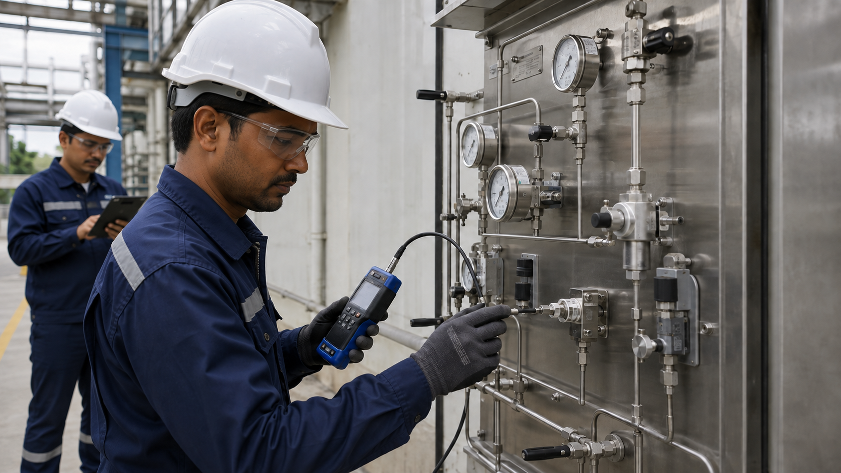
Leak or pressure testing, inspection, functional checks and commissioning as specified for the system, before handover.
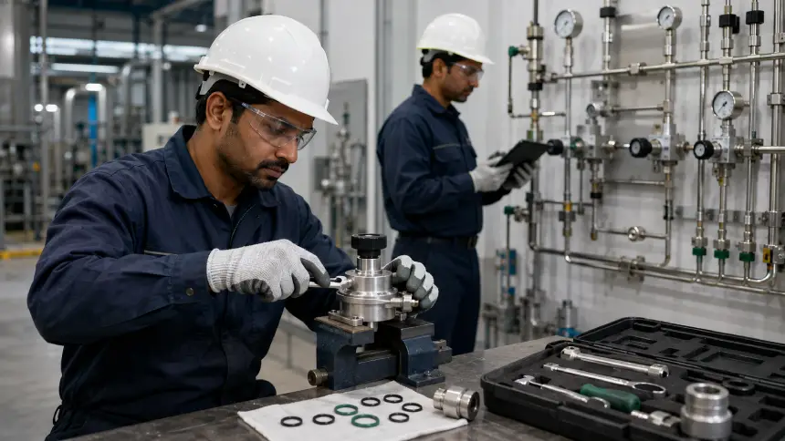
Preventive maintenance, troubleshooting, modifications and ongoing technical support after commissioning.
Engineered testing and detection systems for verifying pressure integrity, identifying leaks and supporting reliable gas-system operation.
Engineering complete gas systems around your process, equipment and operating requirements.
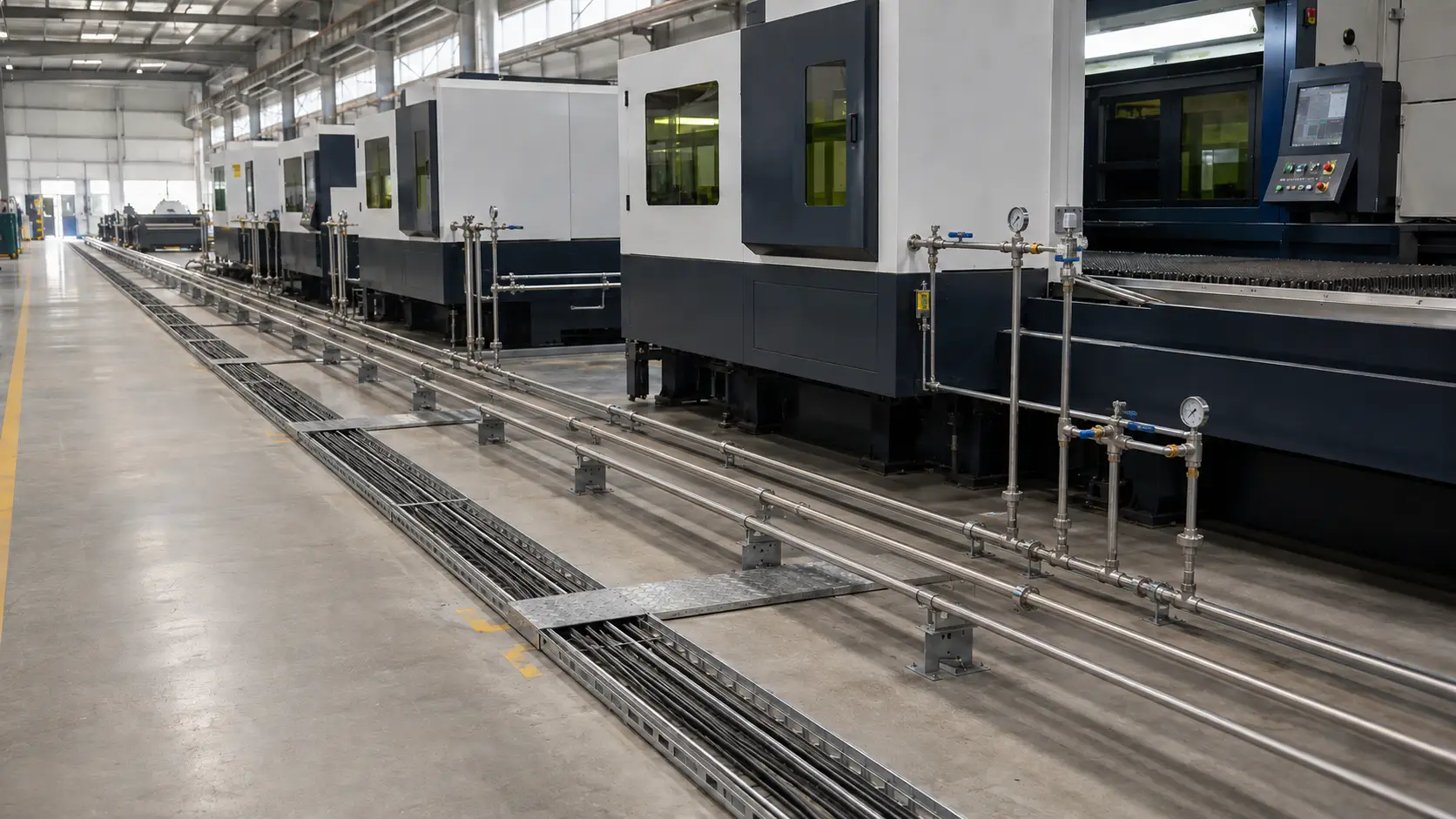
Engineered stainless-steel and copper gas pipeline systems from source to point of use, designed around gas compatibility, pressure, flow, cleanliness, routing, connection technology and downstream equipment requirements.
Engineered gas manifolds for reliable source connection, pressure control and continuous gas supply.
Every field below influences source hardware, line size, regulator selection, materials or site work. Incomplete data delays a defensible arrangement.
Defines materials, cleanliness, seals and protective provisions.
Influences construction, connections and cleaning practice.
Cylinder, bank, bundle or cryogenic storage changes the first-stage architecture.
Sets the rating of source hardware and primary regulation.
Sets primary and point-of-use set-points.
Sizes pipe, regulators and vaporization where used.
Defines branching, isolation and local stations.
Determines whether the source and headers can support coincident use.
Machine, laboratory, process or fabrication duty drives the station layout.
Affects pressure drop, supports and routing.
Influences materials, weather protection and access.
Determines tie-in, isolation and modification work.
May justify spare branches, larger headers or additional source capacity.
Reduce survey time and clarify interfaces.
Access, penetrations, existing services and constraints.
Typical sequence from survey through support. Sequence and deliverables are defined by project scope; not every engagement includes every stage in the same form.
Record sources, routing constraints, equipment locations and operating conditions.
Agree gas, pressures, flow, use points, application and project boundaries.
Define source, primary control, distribution and point-of-use arrangement.
Specify tanks, manifolds, regulators, valves, panels and piping around the operating data.
Produce layouts, line sizing, bills of material and drawings as the project requires.
Build manifolds, panels and pipe or tube assemblies in the workshop where that is in scope.
Route piping, place equipment and make source and point-of-use connections.
Carry out leak or pressure testing, inspection and commissioning according to project scope.
Issue as-built information as required and provide maintenance or AMC support where contracted.
Related: Process page
General information for discussion. It is not project-specific engineering advice.
Materials and seals must match the gas; interchangeability is not assumed.
Cleanliness, dead legs and connection methods follow the purity requirement.
Every regulator and valve must be rated for the actual conditions.
Headers and regulators are sized to both, not to a nameplate average.
Single-stage, two-stage or point-of-use control is selected after review.
Body, wetted parts and supports follow gas, environment and duty.
Seats and seals are gas- and temperature-specific.
Match the pipe or tube specification of the plant.
Source, branch and equipment isolation are defined in the architecture.
Protective devices are included only as the design requires.
Oxygen and high-purity services may need dedicated cleaning practice.
Indoor, outdoor, classified or public areas change hardware selection.
Gauges, regulators and isolation must be reachable.
Spare offtakes and header capacity are considered when the client identifies growth.
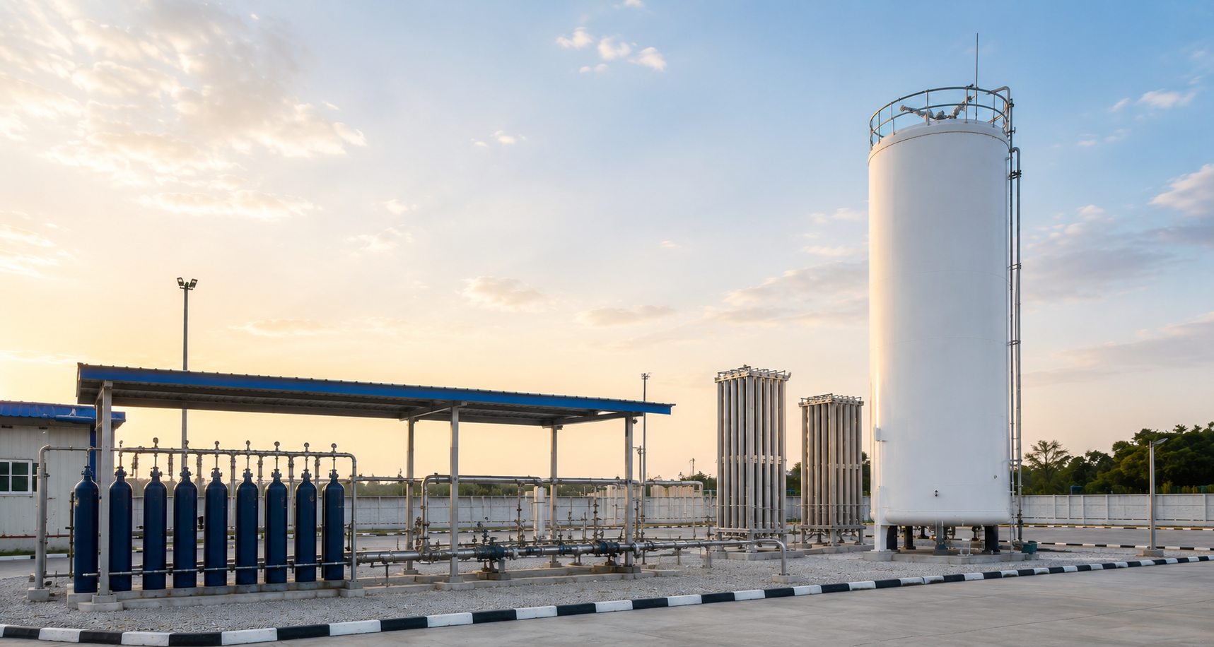
The same source-to-use methods are applied in these operating environments. Sector-specific qualification, including medical or regulatory requirements, is defined per project and is not assumed here.
| Ref | Application area | Typical gas work |
|---|---|---|
| 01 | Industrial plants | Process gas supply and plant distribution |
| 02 | Gas bottling plants | Filling, manifolding and station piping |
| 03 | Pharmaceuticals | Controlled process-gas delivery |
| 04 | Hospitals | Medical gas source, pipeline and outlets as specified per project |
| 05 | Laboratories and R&D | Specialty and research gas points |
| 06 | Automotive and manufacturing | Brazing, welding and production gas |
Prepare the following so engineering can review source, control and distribution without a second round of clarification.