Inlet Connection
Connects the regulator to the gas source or upstream system.
Pressure regulators
Reliable single-stage pressure reduction for controlled gas delivery. A single-stage pressure regulator reduces gas from a higher inlet pressure to a controlled downstream pressure through one primary pressure-reduction stage, providing a practical solution for a wide range of gas supply and distribution applications.
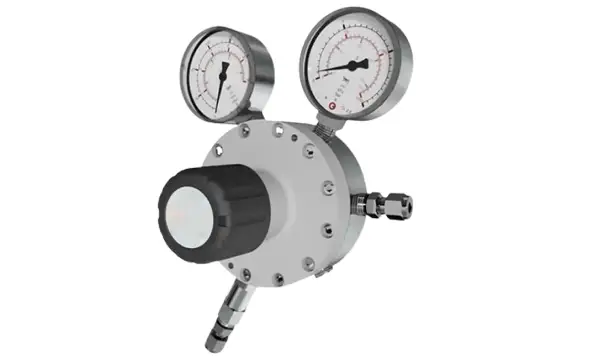
A single-stage regulator reduces inlet pressure to a lower controlled outlet pressure through one pressure-reduction stage. It sits between the gas source and the downstream system so that process equipment sees a usable operating pressure rather than the full source pressure.
The regulator must be selected for the gas, inlet pressure, required outlet pressure, flow demand, temperature and connection configuration. PES treats those fields as part of the gas-system design, not as a catalogue afterthought.
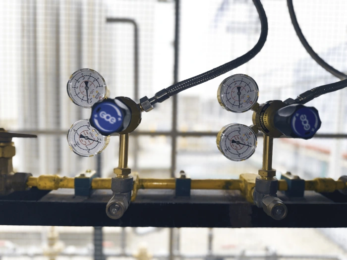
The regulator responds to downstream pressure through its sensing mechanism and adjusts the regulating element to maintain the desired outlet condition. As downstream demand or inlet pressure changes, the diaphragm and spring move the seat to admit more or less gas.
01
Cylinder, manifold or pipeline upstream of the regulator.
02
Interface to the source or upstream pipework.
03
The regulating element that meters gas as pressure is reduced.
04
Senses downstream pressure and sets the target outlet condition.
05
Reduced pressure delivered to the next stage of the system.
06
Pipeline, panel, point of use or process equipment.
The functions below are typical of single-stage industrial regulators. Internal geometry, materials and gauge arrangement vary by configuration and manufacturer datasheet. This is not a claim about one specific PES or OEM model.
Connects the regulator to the gas source or upstream system.
Controls gas flow through the regulator as pressure is reduced.
Senses downstream pressure and transfers pressure changes to the regulating mechanism.
Provides the force used to establish the desired outlet-pressure setting.
Connects the regulated gas supply to the downstream system.
Where provided, indicates inlet or outlet pressure depending on the regulator configuration.
The appropriate configuration depends on the gas service, inlet pressure, outlet-pressure requirement, flow demand and application.
| Feature | Single stage | Double stage |
|---|---|---|
| Pressure reduction | One stage | Two stages |
| Construction | Simpler | More complex |
| Typical use | General pressure reduction | Applications requiring more stable outlet pressure |
| Pressure stability | Dependent on inlet and flow variation | Generally improved across changing inlet conditions |
| Application | Industrial, utility and many general gas systems | High-purity, critical or demanding applications where appropriate |
Two-stage types are covered on the Double Stage Gas Regulator page.
These are typical operating environments. Not every single-stage regulator is suitable for every listed application. Selection follows the gas, pressure, flow and installation conditions of the project.
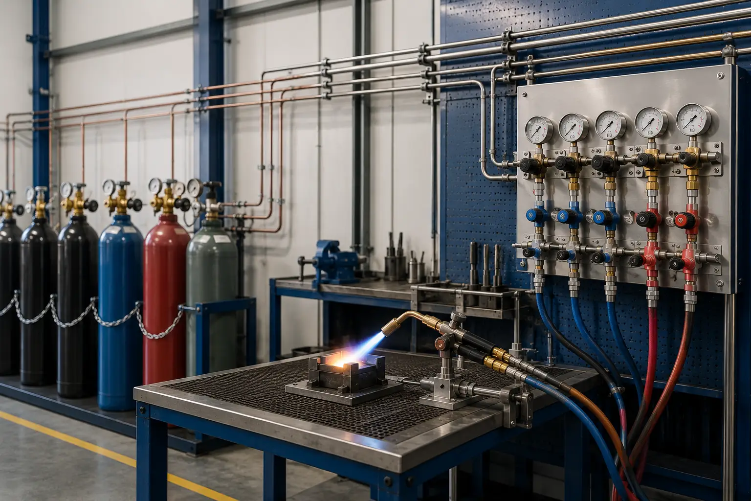
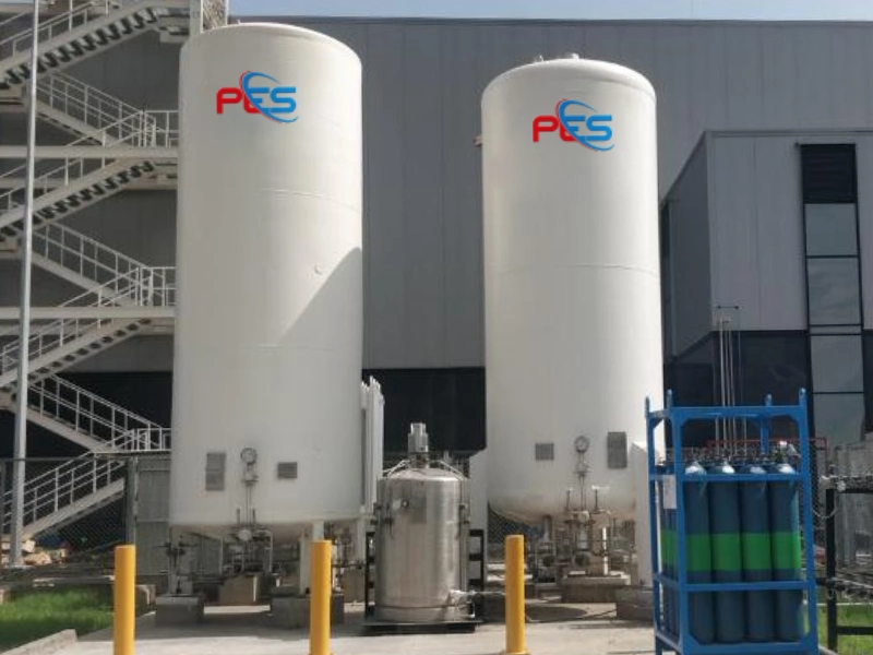
Industrial gas supply
Cylinder gas systems
Gas manifolds
Gas distribution pipelines
Welding and fabrication
Laboratory gas systems
Process gas systems
Point-of-use gas supply
Equipment gas connections
Specialty gas applications
Regulator selection must consider the gas being handled and the materials that come into contact with it. Gas compatibility depends on regulator materials, seals, pressure range, cleanliness requirements and the specific gas service. Always verify compatibility before selection.
Inert and process supply where material compatibility is confirmed for the service.
Requires materials, cleanliness and procedures appropriate to oxygen service. Confirm before selection.
Welding, fabrication and process supply as specified for the application.
Specialty and process service where the regulator construction matches the gas.
Process and utility supply according to pressure, phase and material constraints.
Fuel and process service only where the construction is verified for hydrogen.
Mixture and high-purity services as defined by the gas specification and cleanliness requirement.
For oxygen service, appropriate oxygen-clean components and procedures may be required. One regulator configuration is not automatically compatible with all gases.
Values below are configuration dependent. Exact ratings come from the applicable regulator model and manufacturer datasheet, not from this page.
| Specification | Requirement / available configuration |
|---|---|
| Regulator Type | Single Stage |
| Gas Service | Application specific |
| Inlet Pressure | Application specific |
| Outlet Pressure | Application specific |
| Flow Capacity | Application specific |
| Body Material | Configuration specific |
| Wetted Materials | Configuration specific |
| Diaphragm Material | Configuration specific |
| Seat Material | Configuration specific |
| Inlet Connection | Configuration specific |
| Outlet Connection | Configuration specific |
| Pressure Gauge | Optional / configuration specific |
| Temperature Range | Configuration specific |
| Installation | Cylinder / manifold / pipeline / point-of-use |
Regulator material selection may depend on gas compatibility, pressure, temperature, purity requirements, corrosion resistance, installation environment and required service life.
Potential construction materials include stainless steel, brass or other application-specific materials. A given material is not always suitable for a given gas; compatibility is verified against the service, not assumed from the alloy name.
Regulator configurations may vary according to the installation. Thread standards and dimensions are taken from the project specification, not listed as a default here.
Mounted at the cylinder valve where a cylinder-source arrangement is specified.
Installed on or immediately after a source manifold.
Tube ends matched to the downstream tubing specification.
Threaded ports selected to the pipe or adaptor arrangement in the project.
Fixed in a gas panel or enclosure where the assembly requires it.
Located close to the consuming equipment.
Determine the gas or mixture and the material-compatibility requirement.
Establish the maximum and normal upstream pressure at the regulator.
Identify the required downstream operating pressure.
Consider normal and peak gas consumption of the downstream system.
Choose body, diaphragm and seat materials appropriate to the gas and environment.
Match the regulator connections to the cylinder, manifold, tubing or equipment.
Consider mounting, accessibility, instrumentation and downstream equipment.
Available configurations depend on gas service and project requirements. The list below describes common industrial arrangements; it is not a claim that every configuration is stocked or manufactured by PES for every gas.
01 Cylinder-mounted regulator
02 Manifold-mounted regulator
03 Panel-mounted regulator
04 Point-of-use regulator
05 Pressure-gauge equipped regulator
06 Stainless-steel regulator
07 Brass regulator
08 High-pressure inlet configuration
09 Low-pressure outlet configuration
Regulator selection should consider the complete path rather than treating the regulator as an isolated component.
01
02
03
04
05
06
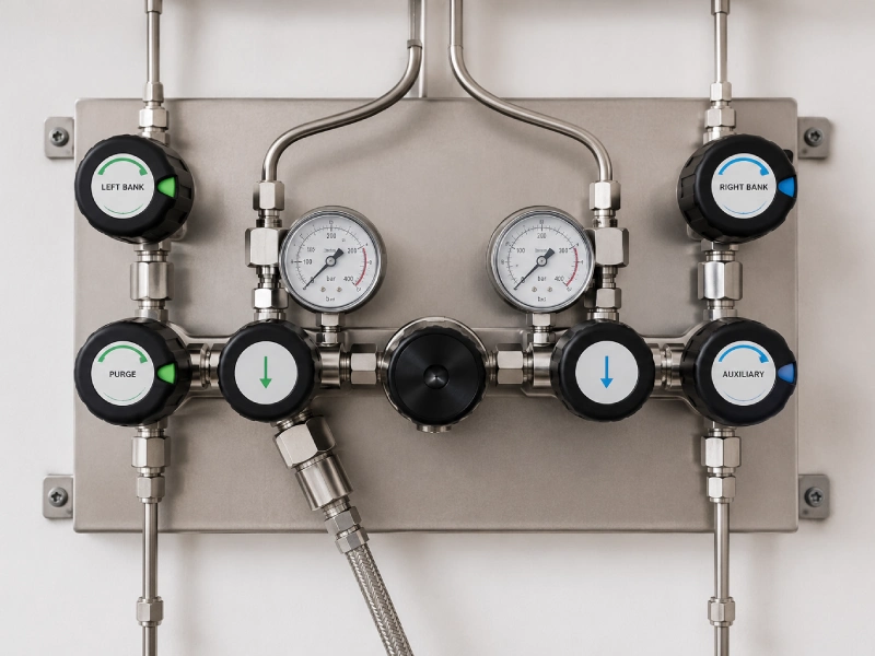
Safe and reliable regulator operation depends on correct gas compatibility, correct pressure selection, appropriate installation, suitable connections, proper inspection, appropriate maintenance, and compliance with applicable project requirements.
This page does not claim a certification, leak-tightness guarantee, or maintenance-free service. Testing and documentation are included according to project scope.
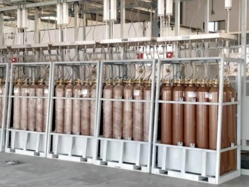
A single-stage gas regulator reduces a higher inlet pressure to a controlled downstream pressure through one primary pressure-reduction stage. The sensing element responds to outlet pressure and moves the regulating element to hold the set condition, within the limits of the selected configuration.
Single-stage regulators reduce pressure in one primary stage. Double-stage regulators use two stages and may provide improved outlet-pressure stability when inlet pressure changes, for example as a cylinder empties. The appropriate type depends on the gas service, inlet variation, outlet requirement and application.
They are used on industrial, cylinder, manifold, pipeline and point-of-use gas systems where one reduction stage meets the pressure-stability requirement. Suitability is determined per application, not by the product name alone.
Only if the selected regulator is rated for that inlet pressure and gas service. Do not assume suitability from the gas type alone. Inlet rating, materials and connections must match the source conditions.
Define the gas, maximum and normal inlet pressure, required outlet pressure, flow, materials, connections and installation location. PES reviews those fields as part of the wider gas-system design.
Only when construction materials, seals, cleanliness and pressure ratings are verified for each gas. Mixing services without that check can be unsafe. Oxygen service in particular may require oxygen-clean components and procedures.
Double-stage regulation may be preferred where outlet-pressure stability under changing inlet conditions is particularly important, such as some high-purity, laboratory or critical process duties. PES will compare both arrangements against the operating data.
Links open published PES pages. High-pressure and high-flow types that do not yet have a dedicated product page open the Gas Regulators family page.
Two-stage types are considered where more stable outlet pressure under changing inlet conditions is required.
View pageSecondary pressure reduction within distribution pipelines, panels and branches.
View pageSpecified where the source pressure requires a high-inlet configuration.
View pageSelected to the flow demand of the downstream system.
View pageSource manifolds and changeover arrangements upstream of regulation.
View pageLine and point-of-use pressure-control arrangements.
View pageRegulators assembled with isolation, filtration and monitoring as specified.
View pageIsolation and flow control around the regulator.
View pageTube, thread and equipment connections on either side of the regulator.
View pageShare your gas type, inlet pressure, required outlet pressure, flow requirement and connection details with the engineering team.