Skip to content

Industrial gas pipeline systems

Gas Pipeline Installation

Engineered stainless-steel and copper gas pipeline systems from source to point of use, designed around gas compatibility, pressure, flow, cleanliness, routing, connection technology and downstream equipment requirements.

Engineering · Material Selection · Installation · Testing · Commissioning

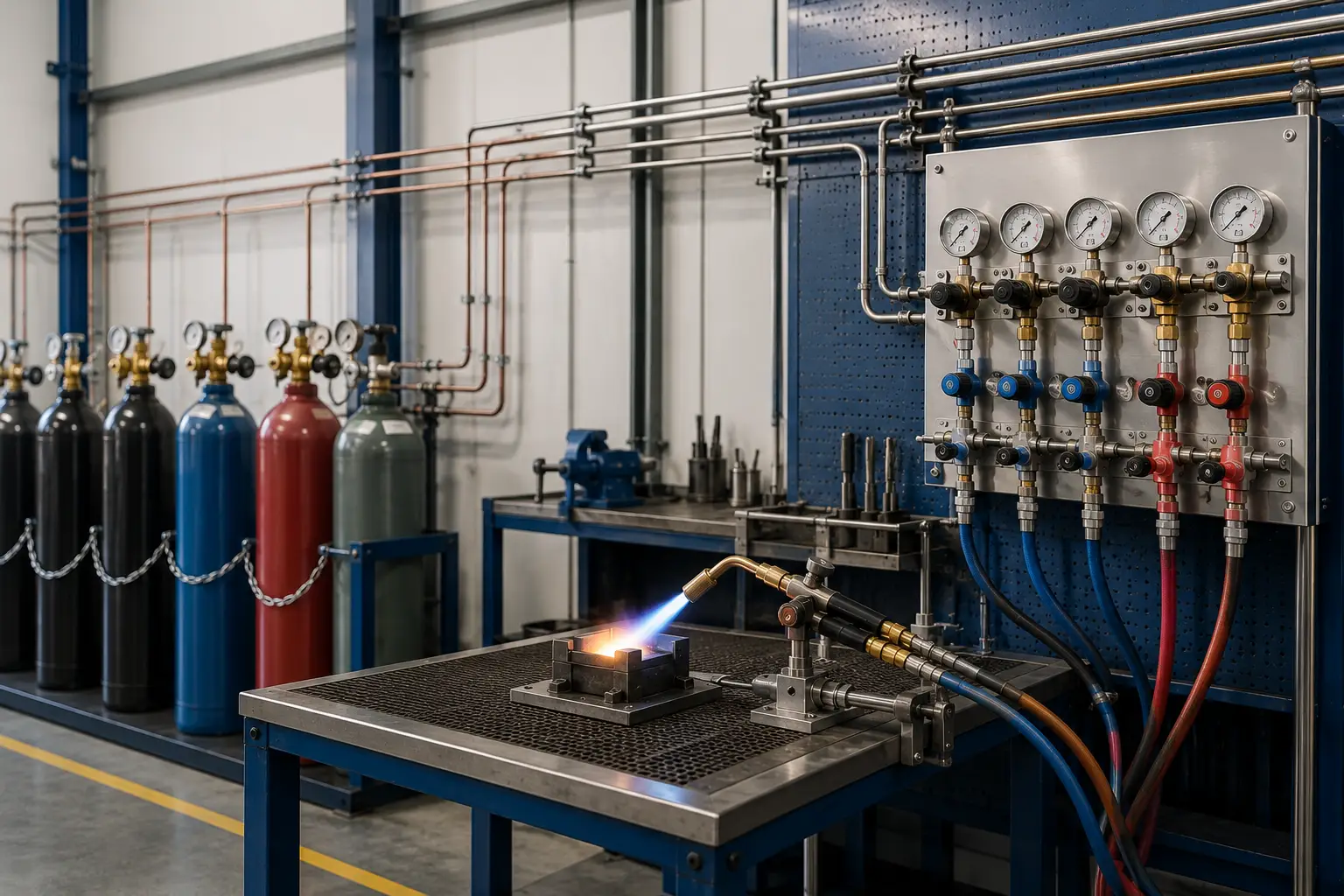
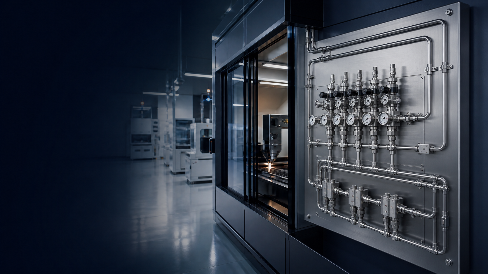
Industrial gas installation with cylinder banks, manifolds and distribution piping
PES industrial gas installation — source equipment through distribution
Scope
Source to point of use
Materials
Stainless steel / copper
Work
Engineer · select · install · test
Position
We do not manufacture tube or fittings
System, not a pipe run

A Gas Pipeline Is a System — Not Just a Pipe

Industrial gas pipeline performance depends on the interaction between the gas source, pressure regulation, tubing, fittings, valves, routing, supports, instrumentation, downstream equipment and installation practices.

A correctly selected tube can still perform poorly if any of the following is true. Likewise, selecting premium fittings alone does not compensate for unsuitable tubing or incorrect installation.

  • The wrong fitting system is used
  • Tubing surface is damaged
  • Tube preparation is poor
  • Components are mismatched
  • Routing introduces unnecessary pressure loss
  • Supports are inadequate
  • Connections are incorrectly assembled
  • Cleanliness is compromised
  • Testing is incomplete

PES evaluates the entire fluid path. Tube + fittings + valves + regulators + installation + supports + testing + commissioning.

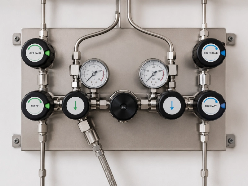
Stainless-steel gas panel with tubing, fittings, valves and gauges
Panel, tube and fittings as one assembly
Architecture

From Gas Source to Point of Use

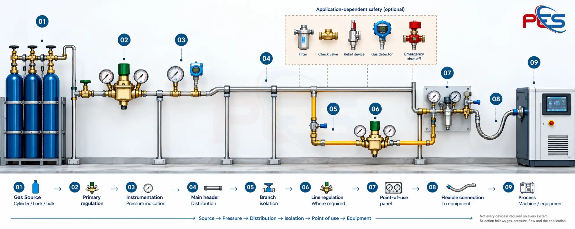
The pipeline is the distribution path that connects engineered source equipment to the process. Optional safety devices are selected where the application requires them — they are not implied on every job.

Drawing 01 — Source to point of use

Typical gas pipeline architecture from gas source through isolation, regulation, main header, branch isolation, line regulation and point-of-use panel to process equipment, with application-dependent safety devices

Fig. 01 — Typical architecture only. Actual system configuration depends on gas, pressure, flow and application requirements.

Material selection

Stainless Steel or Copper?

Neither material is universally superior. The appropriate gas pipeline material depends on gas, purity, maximum pressure, required flow, temperature, corrosion environment, cleanliness, joining method, equipment interfaces, installation environment, applicable project specification and maintenance requirements.

01 / SS

Stainless Steel Gas Tubing

Suitable stainless-steel tubing is commonly selected where the system needs characteristics such as higher pressure capability when appropriately sized, corrosion resistance, clean internal fluid paths, compatibility with precision instrumentation, high-purity construction, robust mechanical properties, reliable integration with engineered tube-fitting systems, and orbital-welded construction where required.

Not all stainless-steel tubing is automatically suitable.

  • Industrial gas systems
  • Specialty gases
  • High-purity gas distribution
  • Instrumentation systems
  • Analytical systems
  • Laboratory systems
  • Process gas systems
  • Gas panels
  • Equipment connections
  • Semiconductor or clean manufacturing where the specification requires it

02 / CU

Copper Gas Tubing

Copper tubing remains an effective material for suitable gas distribution applications when properly selected for the gas service, pressure, cleanliness and installation method.

Ordinary plumbing copper is not automatically suitable. PES does not treat medical-gas certification as a claim that medical-gas systems are a standard offering; those standards are cited only as specification examples.

  • Industrial gas distribution
  • Oxygen systems where specifically suitable
  • Nitrogen
  • Argon
  • Carbon dioxide
  • Laboratory distribution
  • Medical gas systems only when the certified tubing and project specification require it
  • Equipment branch lines
  • Utility gas distribution
Specification

Stainless-Steel Gas Tubing Requires a Complete Specification

Selecting “SS 316” alone is not a complete tubing specification.

Material grade

Use material appropriate to the gas and environmental conditions.

Tubing specification

Select fluid-system tubing to an appropriate tubing specification — not decorative, structural or miscellaneous tube.

Hardness

Tube hardness must be compatible with the selected fitting system.

Wall thickness

Wall thickness affects pressure capability and fitting performance.

Outside diameter

Fitting systems seal and grip around controlled tube dimensions.

Surface condition

Scratches, flat spots, weld seams or defects in the fitting contact area can compromise the connection.

Cleanliness

High-purity and oxygen-related applications may require specific internal cleanliness and handling.

Traceability

Where the project demands it, material documentation and traceability should be considered.

Specification

Not All Copper Tubing Is the Same

Gas-service copper must be selected for its intended application. Copper tubing should be selected by service specification — not merely by diameter.

Material specification

Copper intended for gas service is specified — not assumed from plumbing stock.

Temper

Temper affects formability and mechanical behaviour.

Wall thickness

Wall thickness contributes to pressure capability.

Internal cleanliness

Where cleanliness is critical, appropriately cleaned and capped tubing may be required.

Pressure capability

Capability is configuration and specification dependent.

Manufacturing standard

The applicable standard belongs in the specification, not only the diameter.

End protection

Caps and handling protect the internal surface until installation.

Application certification

Medical-gas copper standards such as EN 13348 / ASTM B819 may apply where that service is specified.

Comparison

Stainless Steel vs Copper Gas Tubing

Engineering comparison of stainless-steel and copper gas tubing
Engineering consideration Stainless steel tubing Copper tubing
Industrial gas distribution Commonly suitable depending on design Suitable for appropriate services
High-pressure capability Strong option when properly sized Application and wall-thickness dependent
High-purity systems Frequently selected Application dependent
Corrosion resistance Strong in many industrial environments; environment still matters Good in suitable environments
Mechanical strength Generally higher Lower than stainless steel
Routing / formability Requires appropriate bending tools and techniques Generally easier to form
Compression tube fittings Widely used Available with compatible fitting systems
Brazed connections Application specific Common joining option where suitable
Orbital welding Strong option for high-purity SS systems Not applicable in the same manner
Cleanliness Available to controlled specifications Special cleaned tubing available
Material cost Typically higher Often economical depending on system
Selection basis Gas + pressure + purity + environment Gas + pressure + cleanliness + application

Neither material is automatically “better.” PES selects the pipeline material around the complete application.

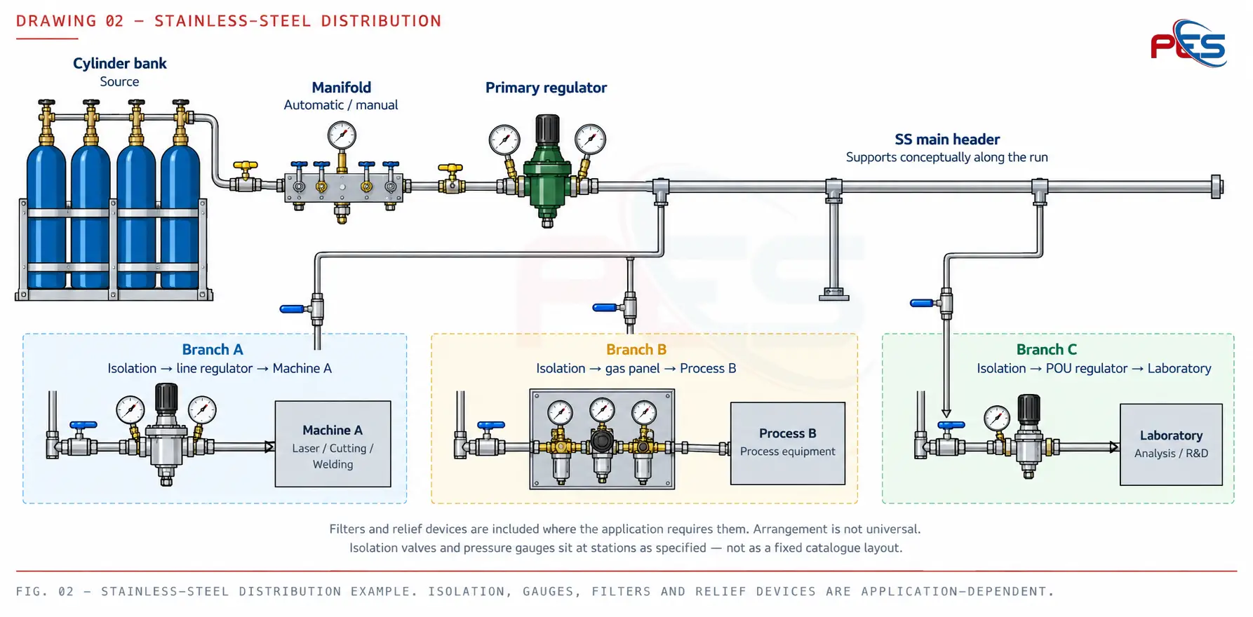
Drawing 02 — Stainless-steel distribution

Stainless-steel gas distribution from cylinder bank and manifold through a primary regulator and SS main header to three branches for a machine, process panel and laboratory

Fig. 02 — Stainless-steel distribution example. Isolation, gauges, filters and relief devices are application-dependent.

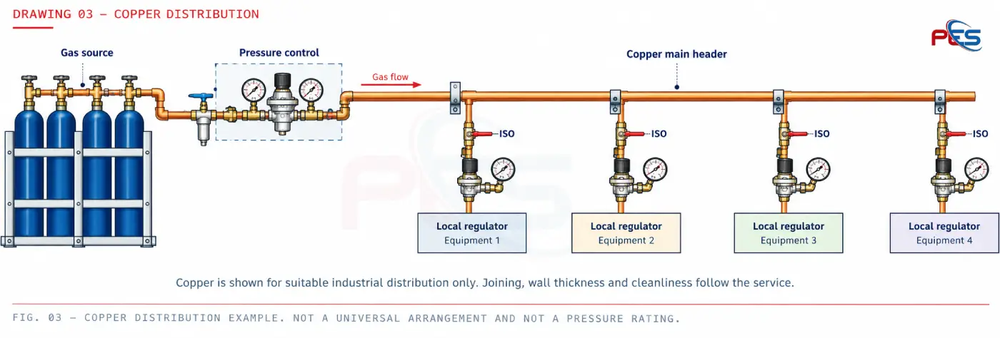
Drawing 03 — Copper distribution

Copper gas distribution from gas source through pressure control and a copper main header to branch isolation and local regulators at equipment

Fig. 03 — Copper distribution example. Not a universal arrangement and not a pressure rating.

Tube fittings

Why the Tube Fitting Matters

Tubing and fittings operate as a system. For mechanical compression-type tube fittings, performance depends on tube dimensions, material, hardness, surface finish, wall thickness, correct tube insertion, correct fitting assembly and proper installer technique.

A high-quality two-ferrule fitting uses a nut to drive a pair of ferrules: the front ferrule forms the primary seal between body and tube; the back ferrule provides a controlled grip on the tube. That is a principle, not a brand claim, and it is not a substitute for the selected manufacturer’s assembly procedure.

Drawing 04 — Two-ferrule connection principle

Generic two-ferrule mechanical tube fitting cross section Original educational section showing tubing, nut, back ferrule, front ferrule and fitting body. Not a proprietary manufacturer drawing. Tubing Nut Back ferrule Front ferrule Fitting body Principle only — original generic schematic Front ferrule: primary seal, body to tube Back ferrule: controlled grip on the tube Nut: drives the ferrule pair during assembly Tube: hardness, OD, wall and surface must suit the fitting Not a manufacturer installation drawing. Assembly procedure follows the selected fitting system. No brand geometry, logos or proprietary dimensions are shown.

Fig. 04 — Educational two-ferrule principle. Tubing and fittings must be treated as a matched system.

Connections

The Connection Is Often the Critical Interface

A gas system contains many connection points. Each one is part of system integrity. Quality fitting systems can provide controlled tube grip, reliable sealing when correctly installed, repeatable assembly procedures, resistance to operational vibration when correctly engineered, reduced dependence on threaded joints throughout small-bore tubing systems, and a maintainable architecture.

Premium fittings still require compatible tubing and correct installation.

Gas distribution panel showing tube connections, valves and gauges
Joining

Different Systems Require Different Joining Methods

Mechanical tube fittings

Used for appropriate stainless-steel and copper tubing systems where maintainable mechanical connections are required. Selection depends on manufacturer system, tube material, hardness, wall thickness, pressure, gas and installation requirements.

Brazed copper connections

May be used in suitable copper gas systems using controlled joining procedures appropriate to the service. Tube preparation, cleanliness, purging where required, correct filler / joining specification and installer workmanship all matter. This is not a brazing procedure.

Routing

Routing Is an Engineering Decision

Headers, drops and isolation are planned around accessibility, unnecessary joints, maintenance access, equipment movement, future expansion, protection from mechanical damage, and separation from incompatible services where the project requires it.

Drawing — Facility routing

Gas source area → main header → production zone → branch drops → gas panels → machines. Routing considers access, isolation, supports, expansion and protection.

Facility routing is an engineering layout decision, not a decorative pipe run.

Flow

The Pipeline Must Deliver Flow — Not Just Pressure

The source can have adequate pressure while the equipment still receives inadequate performance if the pipeline is undersized or restrictive.

  • 01 Required flow
  • 02 Peak demand
  • 03 Simultaneous consumption
  • 04 Pipe / tube internal diameter
  • 05 Pipeline length
  • 06 Number of branches
  • 07 Valves
  • 08 Fittings
  • 09 Regulators
  • 10 Filters
  • 11 Equipment restrictions
  • 12 Allowable pressure drop
  • 13 Future expansion

Drawing — Pressure along the path

Source pressure → regulator → main header → branches → point-of-use pressure. Losses accumulate through length, fittings, valves, filters and restrictions.

Conceptual only. No invented pressure values. Sizing follows demand, allowable drop and the installed path.

Applications

Typical Gas Pipeline Configurations

These are representative architectures. Laser, laboratory and process details vary by equipment manufacturer and project specification.

Header Line reg. Machine

Manufacturing machine

Header → isolation → line regulator → machine

Source Control Header Laser

Laser cutting

Gas source → pressure control → distribution → filtration / final control → laser

Source Manifold Station

Welding & fabrication

Gas source → manifold → pipeline → isolation → workstation

Source Primary POU Instrument

Laboratory

Source → primary regulation → clean distribution → point-of-use regulation → instrument

Source Pipeline Gas panel Equipment

Gas panel system

Source → pipeline → gas panel → controlled equipment supply

Main header M1 M2 M3

Multiple production lines

Main header → branch isolation → local regulation → individual machines

Fabrication station gas supply at a finished point of use
Point-of-use connection after distribution
Oxygen service

Oxygen Requires Additional Consideration

Oxygen service may require application-specific consideration of materials, cleanliness and procedures. Ordinary tubing or components are not automatically oxygen-compatible.

  • Compatible materials
  • Internal cleanliness
  • Oil and grease contamination
  • Component suitability
  • Joining method
  • Installation handling
  • Pressure
  • Flow velocity
  • Applicable project procedures

For oxygen systems, material selection and cleanliness are engineering requirements — not cosmetic preferences. This page does not state ignition thresholds or hazardous operating procedures.

Identification

A Maintainable System Must Be Understandable

Colour codes are not stated here unless a project standard is specified. Identification still belongs in the design.

  • Gas-service identification
  • Flow direction where required
  • Isolation labelling
  • Equipment identification
  • Branch identification
  • Panel identification
  • Consistent routing
Testing

Installation Is Not Complete Until the System Is Tested

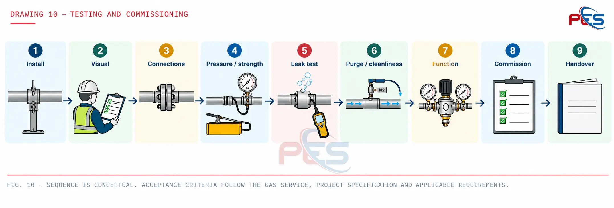
Testing procedures and acceptance criteria should follow the gas service, project specifications and applicable requirements.

Drawing 10 — Testing and commissioning

Conceptual testing and commissioning sequence from installation through inspection, pressure and leak testing, purging, functional verification, commissioning and handover

Fig. 10 — Sequence is conceptual. Acceptance criteria follow the gas service, project specification and applicable requirements.

Explore Leak Testing & Detection
System philosophy

From Components to Complete Gas Infrastructure

Correct tubing Correct fittings Correct valves Correct pressure control Correct installation Correct testing Engineered gas distribution system

PES is not selling pipe by the metre. Quality components plus correct engineering plus correct installation determine the quality of the completed gas pipeline.

Why PES

Why Prema Engineering Services?

01

Application-based selection

Materials and components are selected around the actual gas system.

02

Quality procurement

Components are sourced according to the technical requirements of the project.

03

System integration

The pipeline is considered together with source equipment, regulators, valves, instrumentation and point-of-use equipment.

04

Installation discipline

Attention to tubing preparation, routing, fittings, supports and cleanliness.

05

Testing & handover

System verification according to project scope.

06

Single-system responsibility

Engineering perspective from gas source through distribution to the equipment interface.

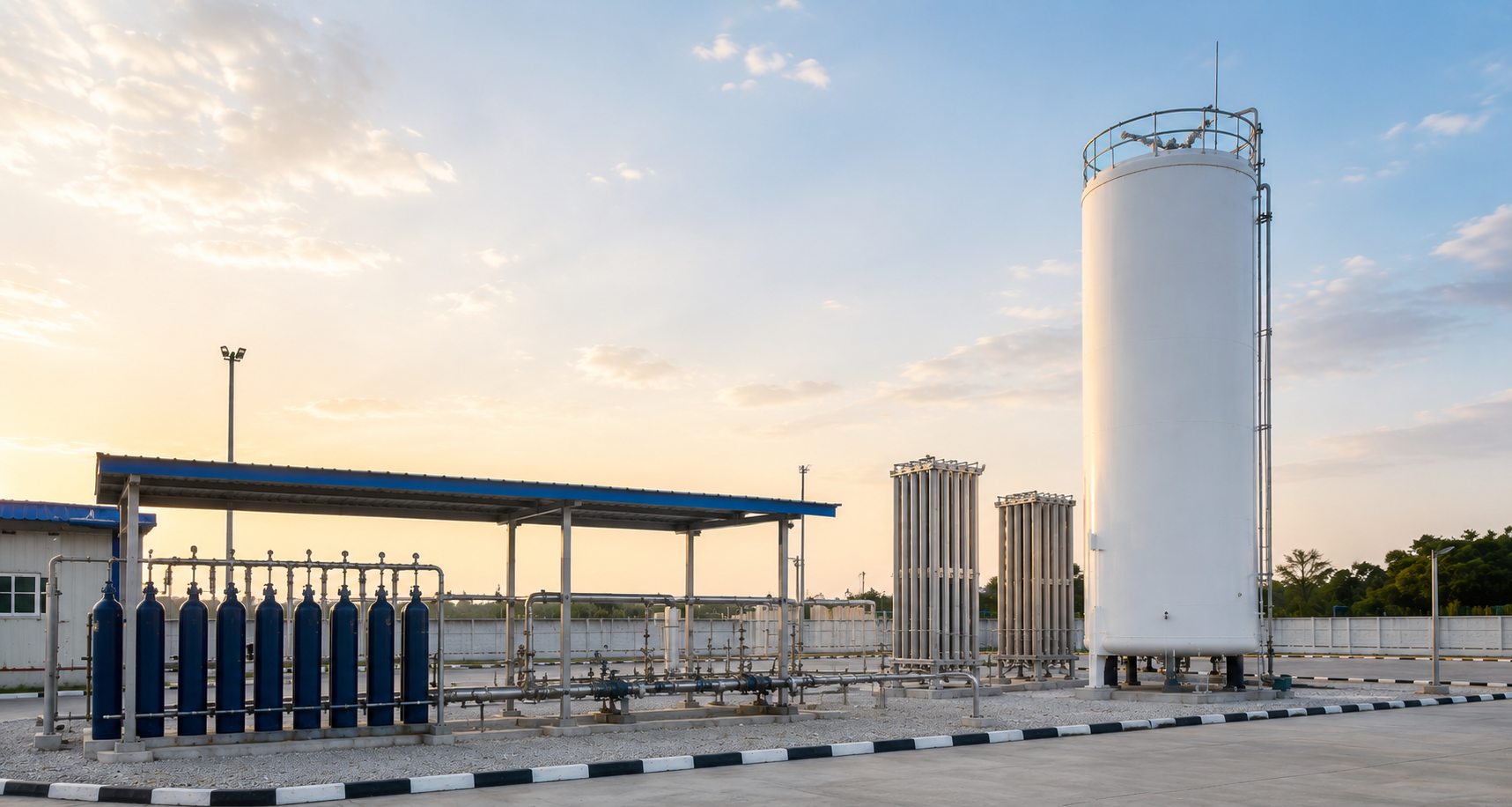
Industrial gas plant piping and equipment
FAQ

Gas Pipeline Installation FAQs

Which is better for gas pipelines — stainless steel or copper?

Neither is universally better. Selection depends on gas, pressure, flow, purity, corrosion environment, joining method and project specification.

Why use stainless-steel tubing for industrial gas systems?

Stainless-steel tubing can provide strong mechanical properties, corrosion resistance and compatibility with precision tube-fitting and welded systems when correctly specified.

Why use copper tubing?

Copper can provide an efficient, workable solution for suitable gas distribution applications where pressure, gas compatibility, cleanliness and joining requirements permit.

Can ordinary plumbing copper be used for industrial gas?

Not as a default. Tubing must be selected according to the required gas service, wall thickness, cleanliness, pressure and applicable specification. Plumbing copper is not automatically suitable.

Is SS 316 enough to specify a gas pipeline?

No. Grade is only one factor. Tubing specification, wall thickness, hardness, dimensions, surface condition, cleanliness and joining system also matter.

Why is tube hardness important?

Mechanical tube fittings depend on controlled interaction between the ferrules and the tube surface, so tubing properties must fall within the fitting manufacturer’s allowable range.

Why does wall thickness matter?

Wall thickness affects pressure capability and can also affect how mechanical tube fittings grip and seal.

Why does surface finish matter?

Mechanical tube fittings seal against the external tube surface, making excessive scratches or defects in the sealing area undesirable.

What type of fitting is used for stainless-steel gas tubing?

Depending on the application, mechanical tube fittings or welded connections may be used.

What is orbital welding?

Orbital welding is a controlled, repeatable fusion-welding process used on stainless-steel tubing where high-integrity joints and cleanliness are specified. High-purity joining is covered on the High-Purity Gas Systems page.

Explore high-purity orbital welding

How is a gas pipeline sized?

Based on gas demand, pressure, allowable pressure drop, line length, branches, components and future requirements.

Does every machine require a regulator?

Not necessarily. Regulation architecture depends on distribution pressure and machine requirements.

How do you test a gas pipeline after installation?

Typical project work includes visual inspection, connection inspection, and project-specific pressure or leak testing, then commissioning. Procedures and acceptance criteria follow the gas service and the specification. This page does not give hazardous test instructions.

Explore leak testing & detection

Does PES manufacture tubing and fittings?

No. Prema Engineering Services engineers, selects, procures and integrates suitable tubing, fittings, valves, regulators and instrumentation according to project requirements. This allows the system to be designed around the application rather than around a single manufactured product range.
Planning an Industrial Gas Pipeline?

Share your gas type, source, operating pressure, equipment flow requirements, pipeline length and point-of-use requirements with our engineering team.