High-Pressure Isolation Valves
Used to positively isolate sections of high-pressure gas systems where appropriate to the valve design and application.
Explore Isolation ValvesValves & Flow Control
Reliable isolation and flow control for demanding high-pressure gas systems. High-pressure valves for isolation, shut-off and controlled gas flow across compressed-gas systems, manifolds, panels, filling stations and industrial gas distribution applications. Selected around the gas service, operating pressure, flow requirement, materials, connection type and system architecture.
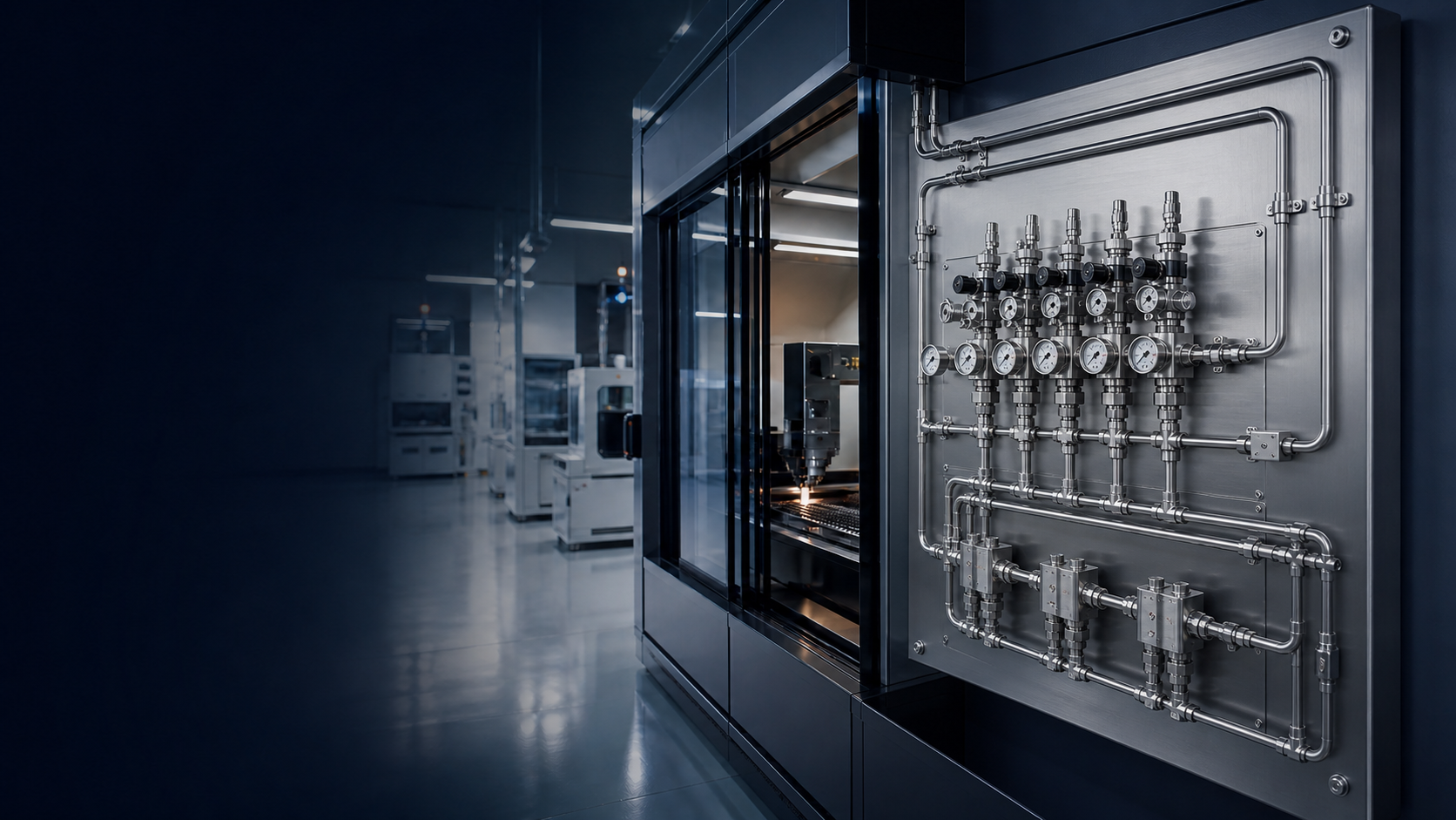
High-pressure gas systems require valves capable of controlling or isolating gas while operating within the pressure, material and compatibility requirements of the system. High-pressure valves may be used between the gas source and pressure-control equipment, within manifolds, filling systems, testing systems, panels and other sections of compressed-gas infrastructure.
The appropriate valve depends on more than pressure alone. Selection should consider gas type, maximum operating pressure, temperature, required flow, valve function, body material, wetted materials, seat and seal materials, connection type, operating frequency and installation environment.
Source isolation → manifold control → pressure regulation → distribution control → equipment isolation.
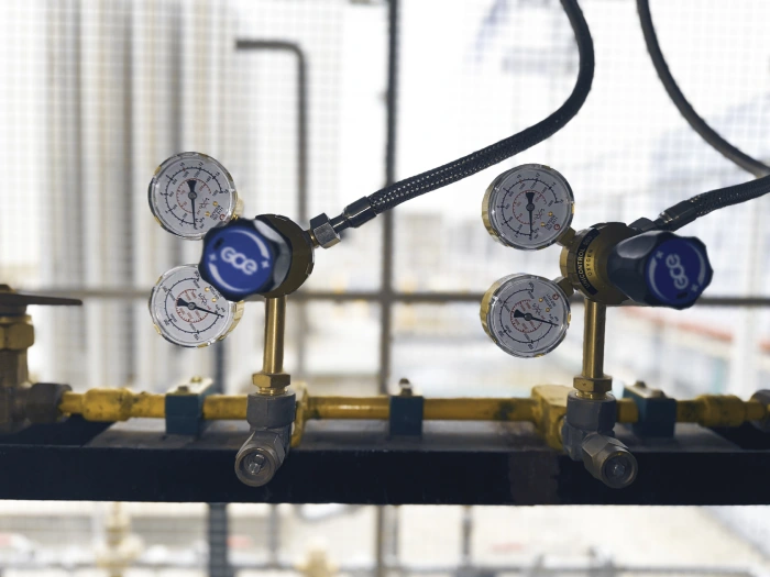
High-pressure valves can perform different functions depending on where they are installed. They may isolate a source, control a manifold branch, prevent reverse flow, provide controlled adjustment or support safe maintenance of sections of the gas system.
01
Compressed-gas source feeding the high-pressure side of the system.
02
Source-side isolation where the system design requires it.
03
Header that combines sources and routes gas toward regulation.
04
Primary reduction from source pressure toward a usable distribution pressure.
05
Pipe or tube carrying gas through the plant or facility.
06
Local isolation, regulation and monitoring at a control assembly.
07
The equipment or process consuming the gas.
High-pressure valves are a family of engineered solutions, not one generic valve. These types are not interchangeable. Dedicated type pages are not published yet; the links below open the matching description on this page.
Used to positively isolate sections of high-pressure gas systems where appropriate to the valve design and application.
Explore Isolation ValvesProvide fine manual adjustment and controlled flow in instrumentation, gas panels and pressure-control systems.
Explore Needle ValvesQuarter-turn valves used for rapid isolation where their construction and pressure rating are suitable for the gas service.
Explore Ball ValvesAllow flow in the intended direction while helping prevent reverse flow.
Explore Check ValvesMay be selected for specialty or high-purity gas systems where appropriate cleanliness and containment characteristics are required.
Explore Diaphragm ValvesPressure-relief devices used as part of an engineered overpressure-protection strategy where applicable.
Explore Pressure Relief Valves| Function | Typical valve category |
|---|---|
| System Isolation | Isolation / ball / application-specific shut-off valve |
| Fine Flow Adjustment | Needle valve |
| Reverse-Flow Prevention | Check / non-return valve |
| Automated Shut-Off | Solenoid / pneumatic valve |
| Pressure Relief | Relief valve |
| Purging / Venting | Needle / purge / vent valve |
| High-Purity Isolation | Application-specific diaphragm valve |
Valve type must be selected according to its intended function, gas service, pressure rating and system requirements.
Isolation valves may be installed to allow specific sections of a gas system to be separated from the pressure source. The exact isolation philosophy should be determined during system engineering and according to applicable project and safety requirements.
Cylinder isolation
Cylinder-bank isolation
Manifold branch isolation
Equipment isolation
Panel isolation
Filling-system isolation
Test-system isolation
Maintenance isolation
Valve configuration and gas compatibility must be verified for the specific application. Not every valve configuration is suitable for every listed environment.
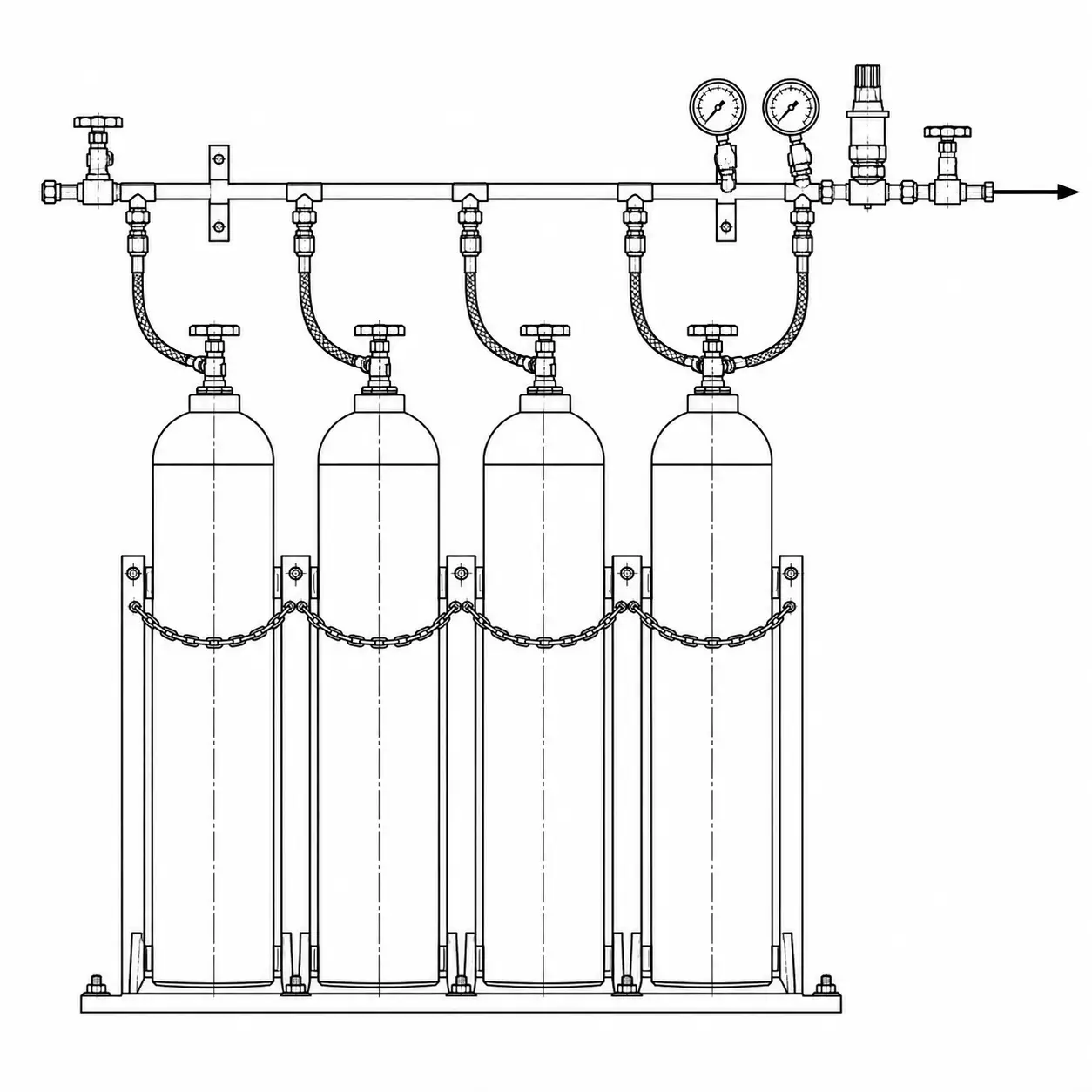
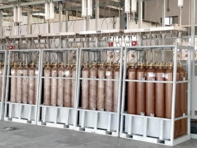
Compressed gas cylinders
Cylinder banks
Gas manifolds
Cylinder quads
Gas cascades
Gas filling stations
Pressure-control panels
Gas distribution systems
High-pressure testing systems
Specialty gas systems
Laboratory gas systems
Industrial process gas systems
Pressure rating alone does not determine valve suitability. Gas compatibility can depend on valve body material, wetted materials, seat material, stem packing, seals, lubricants where applicable, cleanliness, temperature, pressure and operating conditions.
Inert and process supply where body, seat and seal materials are confirmed for the service.
Requires materials, cleaning and oxygen-service procedures appropriate to the application. Confirm before selection.
Welding, fabrication and process supply as specified for the application.
Specialty and process service where leakage and material compatibility are reviewed for the duty.
Fuel and process service only where construction, leakage and materials are verified for hydrogen.
Process and utility supply according to pressure, phase and material constraints.
Mixture and high-purity services as defined by the gas specification and cleanliness requirement.
Application-specific process streams verified against materials, pressure and installation conditions.
For oxygen service, suitable materials, cleaning and oxygen-service procedures may be required. For hydrogen and specialty-gas applications, material and leakage considerations are application-specific. This page does not claim universal gas compatibility.
Values below are configuration dependent. Exact ratings come from the applicable valve model and manufacturer datasheet, not from this page. Numerical pressure, flow, temperature and leakage figures are not listed here.
| Specification | Requirement / configuration |
|---|---|
| Equipment Type | High-pressure gas valve |
| Primary Function | Isolation / control / check / application specific |
| Gas Service | Application specific |
| Maximum Working Pressure | Configuration specific |
| Valve Type | Application specific |
| Body Material | Configuration specific |
| Wetted Materials | Gas / application specific |
| Seat Material | Configuration specific |
| Seal Material | Configuration specific |
| Inlet Connection | Configuration specific |
| Outlet Connection | Configuration specific |
| Port Configuration | Configuration specific |
| Flow Capacity | Configuration specific |
| Operating Temperature | Configuration specific |
| Operation | Manual / pneumatic / solenoid depending on type |
| Installation | Pipeline / manifold / panel / equipment |
Valve construction may include stainless steel, brass, application-specific alloys, compatible seat materials and compatible sealing materials. One material is not universally suitable for a particular gas.
Connection type, size and pressure capability must be selected to match the valve, gas service and surrounding piping system. Specific thread standards and dimensions are not listed here.
Selected to the surrounding high-pressure tube system.
Used where the piping specification calls for that joint style.
Matched to the thread form and pressure capability of the adjacent hardware.
Interface to a header, pigtail or branch on a gas manifold.
Inlet and outlet joints on an assembled gas-control panel.
Specified where the system uses a dedicated high-pressure interface.
Valves can have different internal flow paths and port arrangements depending on their intended function. Port configuration should be selected according to the required system flow path and valve function.
Typical inlet-to-outlet isolation or control.
May be used for selection, diversion, venting or switching depending on valve design.
Used where more complex routing or system functionality is required.
May assist with compact piping layouts where appropriate.
Operated locally using a handle, knob or other mechanical actuator. Suitable where manual isolation or adjustment is required.
May use pneumatic or electrical actuation where remote control, interlocking or automatic shut-off is required.
Automated gas shut-off should be designed as part of the complete control and safety architecture. A single valve does not provide complete system safety.
01
The initiating condition or operator command.
02
Interlock, PLC or dedicated shut-off logic.
03
Pneumatic or electrical actuation as specified.
04
The line being isolated or released according to the control design.
Isolation, flow control, reverse-flow prevention, automated shut-off or pressure relief.
Determine gas-compatibility requirements.
Establish the maximum pressure the valve may experience.
Evaluate normal and peak gas flow.
Choose body, wetted, seat and seal materials appropriate to the service.
Match the valve to the surrounding tube, manifold, panel or equipment.
Manual, pneumatic, solenoid or another application-specific configuration.
Consider regulators, manifolds, gauges, relief devices, pipelines and downstream equipment.
Appropriately selected valves allow individual cylinder branches and sections of the manifold to be isolated where required by the system design.
01
First source branch, isolated independently where the design requires it.
02
Second source branch on the same header.
03
Further source branches as specified for the bank.
04
Combines the isolated branches into one source path.
05
Isolates the manifold from downstream regulation.
06
Reduces source pressure toward distribution pressure.
07
Continues into pipeline, panel or process.
Valves are often integrated with regulators, instrumentation and safety components within engineered gas-control assemblies.
01
Gas entering the panel from the source or distribution line.
02
Inlet isolation for maintenance and commissioning.
03
Indication where instrumentation is specified.
04
Pressure reduction within the panel.
05
Relief, filtration or additional isolation as specified.
06
Downstream isolation before the distribution connection.
07
Leave the panel toward the process or further piping.
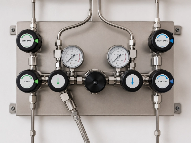
Selecting a high-pressure valve is only one part of the complete system design. Prema Engineering Services selects and integrates valves as part of the industrial gas system, rather than as standalone components.
A single valve does not provide complete system safety. Testing and documentation are included according to project scope.
A high-pressure gas valve is designed to isolate, control or direct gas within a system operating within the valve’s specified pressure range.
Common categories include isolation valves, needle valves, ball valves, check valves, diaphragm valves and application-specific control or relief valves. These types are not interchangeable.
Selection should consider valve function, gas type, maximum pressure, temperature, flow, materials, connections and operating requirements.
Not automatically. Compatibility must be verified for the specific gas, materials, seals, cleanliness requirements and operating conditions.
A needle valve is commonly used where controlled adjustment or fine flow control is required. An isolation valve is primarily selected to shut off or isolate a section of the system.
A check valve operates automatically to help prevent reverse flow. An isolation valve is operated to separate one part of the system from another.
Certain valve configurations can use pneumatic or electrical actuation. Suitability depends on the valve and application. Automated shut-off should be designed as part of the complete control and safety architecture.
Provide gas, maximum pressure, normal operating pressure, required valve function, flow requirement, connection type, material preference if specified, temperature, installation arrangement, and automation requirements if applicable.
Isolation, needle, ball, check, diaphragm and solenoid cards open the matching section on this page until dedicated product pages are published. Thermal and pressure relief open Filtration & Safety. Manifolds, regulators, gauges and panels open their published pages.
Source, manifold, panel and equipment isolation as specified for the duty.
On this pageFine adjustment and controlled flow in panels and instrumentation.
On this pageQuarter-turn isolation where the construction suits the gas service.
On this pageHelp prevent reverse flow in the intended direction of travel.
On this pageSpecialty and high-purity isolation where that construction is required.
On this pageProtection of isolated sections against temperature-driven pressure rise, selected with the wider safety arrangement.
View pageOverpressure-protection devices specified as part of the engineered system.
View pageElectrical actuation where remote or interlocked shut-off is specified.
On this pageSource headers and changeover arrangements that use high-pressure isolation.
View pagePressure reduction downstream of source isolation.
View pageIndication of inlet and outlet conditions around isolation and regulation.
View pageAssembled isolation, regulation and monitoring at a control point.
View pageShare your gas type, maximum pressure, valve function, flow requirement, connection details and installation requirements with our engineering team.