Local Pressure Control
Establish the pressure required by a specific branch or piece of equipment.
Pressure regulators
Precise downstream pressure control for industrial gas distribution systems. Line regulators provide secondary pressure reduction and controlled gas delivery within industrial, laboratory, specialty and process gas distribution systems. They are typically installed downstream of the primary source regulator, manifold or pressure-control system to establish the pressure required by a distribution branch, process area or point of use.
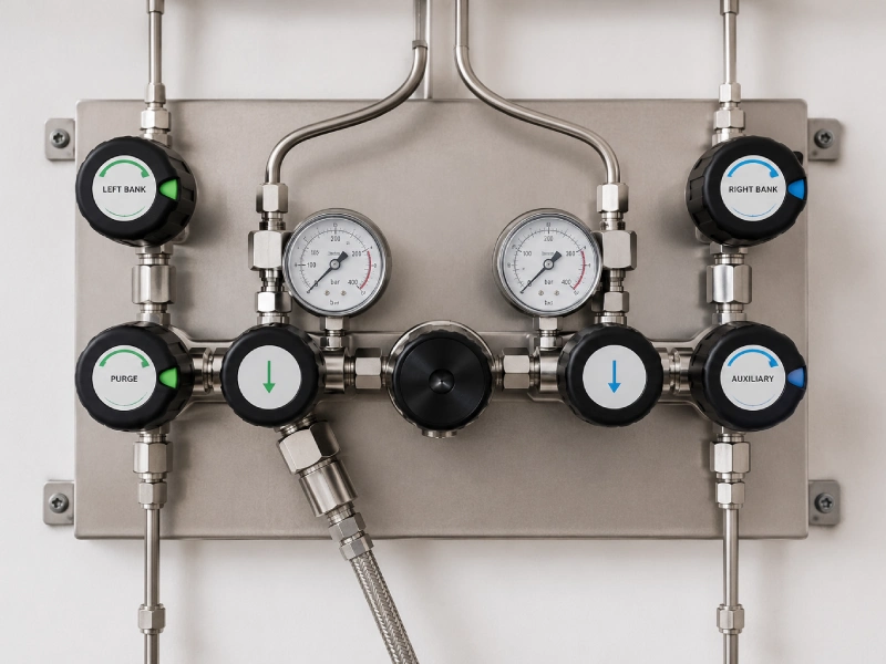
A gas system may require pressure reduction at more than one location. The primary regulator located near the cylinder, manifold, tank or gas source typically reduces source pressure to a suitable distribution pressure.
A line regulator can then be installed further downstream to reduce that pressure again to the level required by a particular branch, machine, laboratory, process or point-of-use station. Line regulators can therefore help create different pressure zones within a common gas distribution system.
Source regulation → distribution pressure → line regulation → point-of-use pressure.
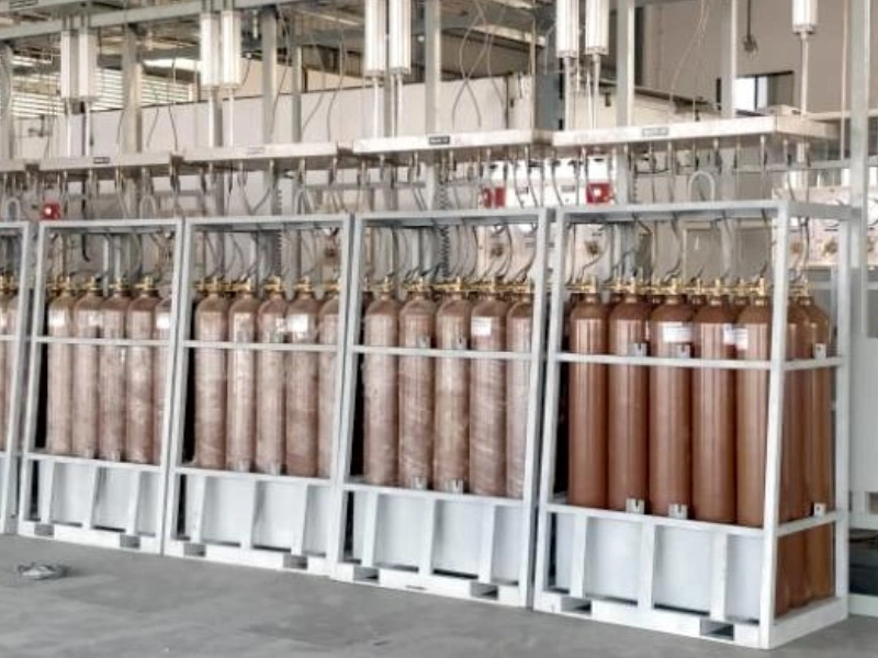
Unlike a cylinder regulator, a line regulator is generally installed within the downstream distribution system where pressure must be controlled closer to the process or equipment being supplied.
01
Cylinder, cryogenic tank or other upstream supply.
02
Source-side pressure reduction and bank management.
03
The header that carries regulated distribution pressure.
04
Secondary reduction to the pressure required by a branch or area.
05
Indication of the downstream condition where instrumentation is specified.
06
Isolation of the branch, station or equipment as required by the design.
07
The consuming equipment or final delivery point.
Establish the pressure required by a specific branch or piece of equipment.
Allow different areas of the same gas system to operate at different downstream pressures.
Help prevent downstream equipment from being exposed to higher distribution pressures than required.
Provide pressure adjustment closer to the process consuming the gas.
Support larger facilities where gas is distributed across multiple departments or machines.
Allow additional branches or equipment to be integrated with appropriate downstream pressure control.
| Feature | Cylinder / primary regulator | Line regulator |
|---|---|---|
| Typical location | Gas source | Distribution pipeline |
| Primary function | Reduce source pressure | Secondary pressure reduction |
| Installation | Cylinder / manifold / source | Pipeline / panel / point of use |
| Upstream source | Cylinder or manifold pressure | Regulated distribution pressure |
| Downstream supply | Distribution system | Equipment, branch or process |
| Typical purpose | Establish system supply pressure | Establish local operating pressure |
Exact system architecture depends on gas type, pressure, flow requirements and the overall gas distribution design.
Explore single stage regulatorsIn some systems these functions may overlap depending on the layout and equipment configuration.
Can control pressure for a downstream distribution branch, production area or group of equipment.
Typically provides final pressure adjustment immediately before an individual machine, instrument or process.
Regulator configuration and gas compatibility must be verified for the specific application. Not every line regulator is suitable for every listed environment.
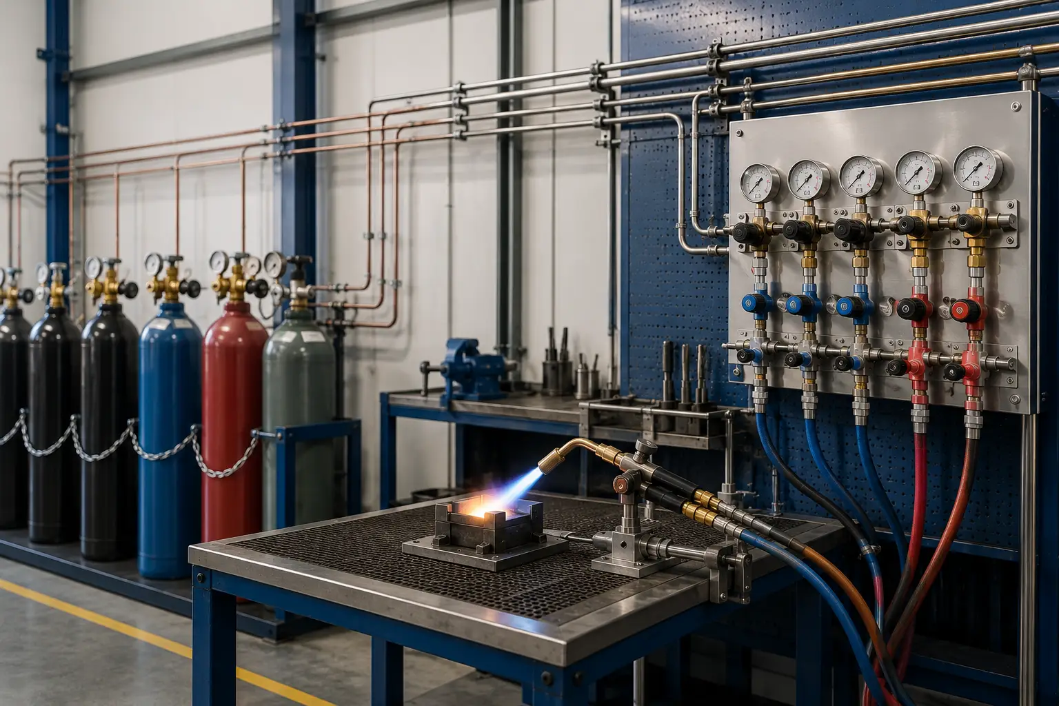
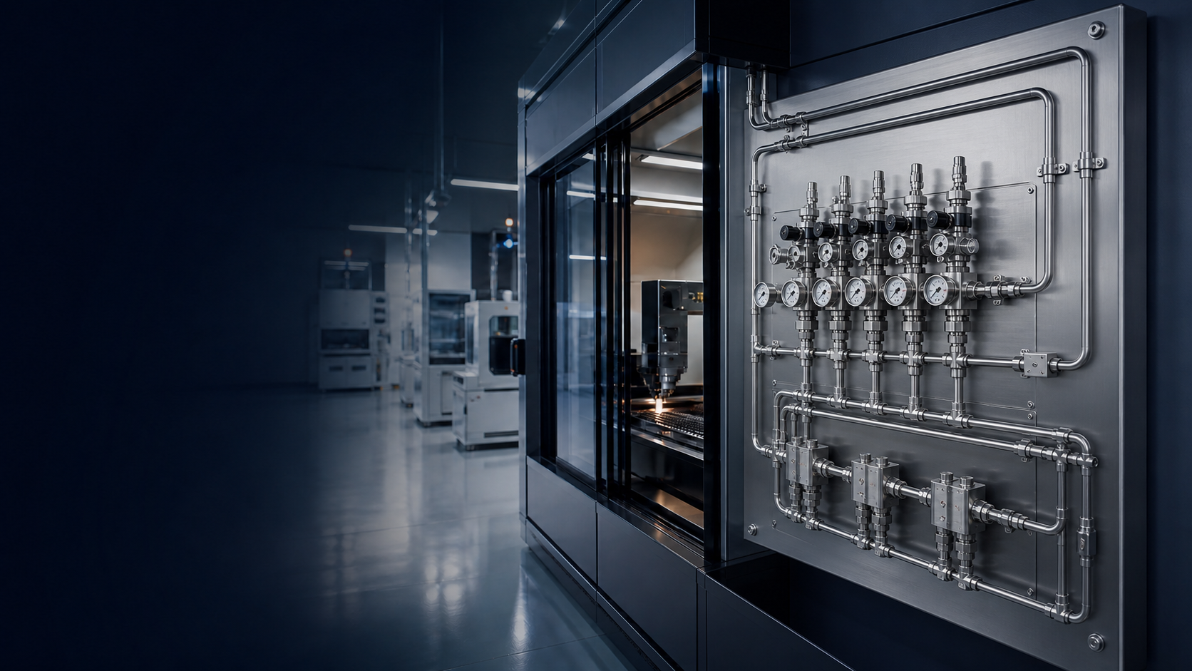
Industrial gas pipelines
Manufacturing equipment
Laser and cutting gas systems
Welding gas distribution
Laboratory gas systems
Specialty gas distribution
Pharmaceutical facilities
Research laboratories
Analytical instruments
Process gas systems
Food and beverage gas systems
Gas panel installations
Gas compatibility depends on regulator construction materials, wetted components, seats, seals, cleanliness, pressure and application requirements. One regulator configuration is not automatically compatible with all gases.
Inert and process supply where material compatibility is confirmed for the service.
Requires materials, cleanliness and procedures appropriate to oxygen service. Confirm before selection.
Welding, fabrication and process supply as specified for the application.
Specialty and process service where the regulator construction matches the gas.
Process and utility supply according to pressure, phase and material constraints.
Fuel and process service only where the construction is verified for hydrogen.
Utility air only where the regulator construction matches the service and cleanliness requirement.
Mixture and high-purity services as defined by the gas specification and cleanliness requirement.
Application-specific process streams verified against materials, pressure and installation conditions.
For oxygen service, appropriate oxygen-compatible materials and cleanliness procedures may be required.
The exact valve, gauge and pressure-protection arrangement should be determined by the system design and project requirements. This diagram is not a universal mandatory configuration. Additional safety components are application-specific.
01
The distribution line carrying pressure into the station.
02
Upstream isolation as specified for the station.
03
Inlet indication where instrumentation is included.
04
Secondary pressure reduction for the branch or equipment.
05
Outlet indication where instrumentation is included.
06
Downstream isolation as specified for the station.
07
The consuming equipment or continuing distribution path.
Values below are configuration dependent. Exact ratings come from the applicable regulator model and manufacturer datasheet, not from this page.
| Specification | Requirement / configuration |
|---|---|
| Product Type | Line gas regulator |
| Function | Secondary pressure reduction |
| Gas Service | Application specific |
| Inlet Pressure | Configuration specific |
| Outlet Pressure | Configuration specific |
| Flow Capacity | Configuration specific |
| Regulation | Single / multi-stage depending on configuration |
| Body Material | Configuration specific |
| Wetted Materials | Gas specific |
| Diaphragm Material | Configuration specific |
| Seat Material | Configuration specific |
| Inlet Connection | Configuration specific |
| Outlet Connection | Configuration specific |
| Pressure Gauge | Optional / system specific |
| Mounting | Inline / panel / wall / point-of-use |
| Temperature Range | Configuration specific |
Line-regulator material selection depends on gas compatibility, purity requirements, pressure, temperature, corrosion resistance, installation environment and process requirements. A given material is not always suitable for a given gas.
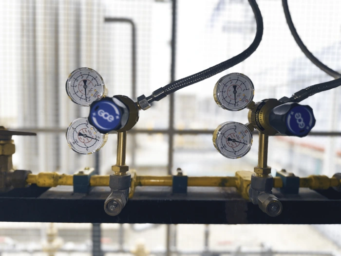
Line regulation can allow a common upstream gas supply to feed multiple downstream branches requiring different operating pressures. Numerical set-points are defined per project, not on this page.
Central gas source
Main distribution pressure
Line regulator → Pressure Zone A
Line regulator → Pressure Zone B
Line regulator → Pressure Zone C
Selecting a line regulator based only on pressure is insufficient. The regulator should also support the gas-flow requirements of the downstream equipment.
Expected continuous consumption of the downstream equipment or branch.
Maximum temporary demand that the regulator must support.
Available pressure upstream of the line regulator.
Pressure required by the downstream equipment.
How stable the downstream process pressure needs to remain.
Potential additional equipment or branch expansion.
Confirm the gas and material compatibility requirements.
Establish the pressure present in the upstream distribution line.
Determine the operating pressure required downstream.
Establish normal and peak flow requirements.
Consider how stable downstream pressure must remain under changing demand.
Choose suitable materials for the gas and service environment.
Match the regulator to the pipe or tube distribution system.
Consider instrumentation, isolation and pressure-relief requirements.
Available configurations depend on gas service, pressure, flow and project requirements. This is not a claim that every configuration is stocked or manufactured by PES for every gas.
01 Stainless-steel line regulator
02 Brass line regulator
03 High-purity line regulator
04 High-flow line regulator
05 Panel-mounted line regulator
06 Inline gas regulator
07 Point-of-use line regulator
08 Gauge-equipped line regulator
Line regulators can also be integrated into engineered gas panels. Final panel content is selected according to the gas service and project requirements.
Prema Engineering Services can integrate line regulation with gas sources, manifolds, pressure-control systems, pipelines, instrumentation, isolation valves, safety components and point-of-use equipment.
01
02
03
04
05
06
07
Appropriate line-regulator operation depends on correct gas compatibility, maximum upstream pressure, required downstream pressure, flow capacity, component pressure ratings, correct installation, isolation, instrumentation, pressure protection where required, appropriate testing, and manufacturer maintenance requirements.
This page does not claim leak-tightness, zero failure, maintenance-free service, universal gas compatibility or guaranteed safety. Testing and documentation are included according to project scope.
A line regulator is a pressure regulator installed within a gas distribution pipeline to reduce upstream line pressure to the pressure required by a downstream branch, process or piece of equipment.
A cylinder regulator normally performs primary pressure reduction at the gas source. A line regulator generally performs secondary pressure reduction further downstream.
It may be installed in a gas pipeline, gas panel, distribution branch or near the point of use depending on system requirements.
Yes. Properly engineered systems may use multiple line regulators to establish different pressure zones for different processes or equipment.
This depends on the regulator materials, seals, seat construction, cleanliness and pressure configuration. Compatibility must be verified for each gas service.
Provide gas type, available inlet pressure, required outlet pressure, normal and peak flow, connection details and installation requirements. PES reviews those fields as part of the gas-system design.
Both provide pressure reduction, but terminology and equipment construction can differ depending on the gas system and application.
No. The need for secondary or point-of-use regulation depends on the distribution pressure and equipment operating requirements.
Links open published PES pages. High-pressure and high-flow types that do not yet have a dedicated product page open the Gas Regulators family page. Point-of-use regulation is covered on Pressure Control until a dedicated page is published.
Primary reduction through one stage at source, manifold or point of use.
View pageTwo-stage types where outlet-pressure stability under changing inlet conditions is required.
View pageSpecified where the source pressure requires a high-inlet configuration.
View pageSelected to the flow demand of the downstream system.
View pageFinal pressure adjustment close to an individual machine or process.
View pageSource manifolds and changeover arrangements upstream of distribution.
View pageRegulators assembled with isolation, filtration and monitoring as specified.
View pageInlet and outlet indication as specified with the station.
View pageIsolation around the line-regulator station.
View pagePressure-protection components selected with the wider safety arrangement.
View pageShare your gas type, available inlet pressure, required outlet pressure, flow demand and connection requirements with our engineering team.