Pressure Instruments
Local gauges and electronic transmitters for source, regulated, header and point-of-use pressure. Transmitters, gauges, switches and differential-pressure devices for source, line and process-side measurement.
Pressure & Instrumentation
Pressure, temperature and vacuum instrumentation for monitoring critical operating conditions across industrial gas, specialty gas, process and pressure-control systems.
Selected around measurement range, gas service, connection, accuracy, operating environment and system architecture.
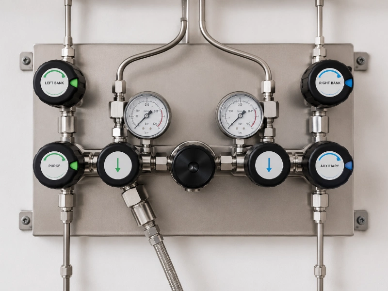
Pressure, temperature and vacuum measurements provide visibility into operating conditions across industrial gas systems. The correct instrument and measurement location depend on what must be monitored — source pressure, regulated pressure, process temperature, vacuum condition or equipment status.
PES selects and integrates instrumentation according to measurement point, range, gas compatibility, connection, accuracy, environment and required function.

A measurement is only useful when the instrument sits at the right point in the gas train. The path below is a representative arrangement, not a universal P&ID.
01
Cylinder, bulk vessel or plant header feeding the gas train.
02
Source-side isolation so the instrument and downstream equipment can be maintained.
03
Indication or transmission of the unregulated source condition.
04
Primary reduction toward a usable distribution pressure.
05
Confirmation of the controlled downstream pressure.
06
Discrete signal for a defined high, low or abnormal condition.
07
Main header carrying gas toward branches and equipment.
08
Local measurement at the process, chamber or production asset.
Representative arrangement only. Ranges, alarm set points, materials and connections follow the application duty. Not for construction.
Selected around the measurement objective and installation environment. These families are not interchangeable.
Local gauges and electronic transmitters for source, regulated, header and point-of-use pressure. Transmitters, gauges, switches and differential-pressure devices for source, line and process-side measurement.
Sensors and indicators for gas condition, ambient exposure, process equipment and heated assemblies. RTDs, thermocouples and temperature switches selected for process stability, compensation and protection.
Vacuum gauges, transducers and switches selected for evacuation, hold testing and low-pressure process conditions.
Discrete switches and transmitted signals for alarms, permissives, shutdowns and remote indication. Position, flow and alarm devices that confirm system or component condition.
The function determines the instrument output, integration method and response required. From signal to system response: observe the condition, recognise deviation, then act on the signal.
Provides local or remote visibility of an operating value.
Typical: gauge or indicator
See the condition. Continuous indication of pressure, temperature or vacuum at the point where operating visibility matters.
Identifies a defined high, low or abnormal condition and initiates a signal.
Typical: switch or alarm
Recognise deviation. Switches, alarms and status signals identify unsafe limits, loss of supply or equipment malfunction.
Feeds a controller or interlock to regulate equipment and process response.
Typical: transmitter + logic
Act on the signal. Transmitters and integrated devices support regulation, interlocks and reliable process decisions.
PES reviews the measurement location, normal and maximum range, gas and wetted-material compatibility, process connection, accuracy, ambient conditions, ingress protection, hazardous-area needs, display requirements and electrical output before specifying an instrument.
Normal and maximum measurement range, with accuracy matched to the duty.
Gas and wetted-material compatibility for the intended service.
Process connection, ambient conditions, ingress protection and hazardous-area needs.
Local display, electrical output and whether the instrument must monitor, detect or control.
An instrument does not operate independently of the system around it. Wetted materials, process connection, mounting arrangement, accessibility and installation method all influence whether a gauge or switch is appropriate for the intended gas service.
Process source → safe isolation → leak-tight interface → readable output. Not to scale.
Confirm body, diaphragm, seals and fittings are compatible with the gas chemistry, purity requirement, temperature range and potential condensate.
Match thread, flange, tube or welded connection details to the pressure class and leakage performance required by the installation.
Use a stable, supported position that limits vibration, protects the instrument from impact and keeps the dial or switch accessible for inspection.
Allow room to isolate, vent, calibrate and replace the instrument without disturbing the main pipeline or compromising operator safety.
Preferred
The instrument is upright, visible, supported and isolated from the process for safe maintenance.
Avoid
An unsupported side-load, awkward orientation or inaccessible connection increases maintenance risk and measurement uncertainty.
Treat the connection as part of the instrument specification. A pressure rating alone does not establish suitability. Review the complete gas path, isolation method, material compatibility, mounting orientation and access requirements before approving the installation.
Measurement instruments can drift over time due to ageing, pressure cycling, vibration, temperature, mechanical shock and operating conditions. Periodic calibration verifies whether an instrument continues to perform within the accuracy required by the application.
Traceable reference standards and controlled inputs.
Multiple points distributed across the measurement range — lower, mid and upper range as required by the duty.
01
Connect and stabilize the instrument before measurement.
02
Apply stable, repeatable inputs at defined test points.
03
Compare the indication against a traceable reference value.
04
Capture indicated value, reference value and deviation.
05
Assess the result against the application tolerance.
06
Confirm conformity or identify the need for adjustment.
07
Document results, conditions, traceability and next due date.
Instrumentation reliability depends on more than initial selection. Instruments should be installed correctly, inspected during service, periodically verified and supported by records that allow maintenance teams to understand calibration history, replacement and system changes.
01
Define range, accuracy and criticality.
02
Mount, connect and protect correctly.
03
Confirm operation and baseline data.
04
Check condition, installation and trends.
05
Compare performance with a reference.
06
Assess drift, risk and next action.
07
Return the decision to service planning.
08
Capture history and system changes.
Record update feeds the next selection and verification cycle.
Use the same practical checks during service rounds, before verification and after maintenance or system changes.
Look for damage, corrosion, contamination, loose hardware, cracked displays or compromised seals.
Confirm supports, impulse lines, cables, fittings and protective devices remain secure and correctly routed.
Check readable indication, stable output, alarms, status signals and communication with the control system.
Review temperature, vibration, pressure, exposure and process conditions against the intended application.
Compare current readings with operating history and note unexplained drift, intermittent behaviour or repeated alarms.
Verify asset identification, calibration status, due date, work orders and changes are recorded consistently.
Decision point
A result within expectations supports continued service. A result outside expectations may require adjustment, investigation, repair, replacement or review of the verification interval.
Record essentials
Values below are configuration dependent. Exact ranges, accuracy and connection details come from the applicable instrument model and manufacturer datasheet, not from this page. Numerical pressure, temperature and vacuum figures are not listed here.
| Specification | Requirement / configuration |
|---|---|
| Equipment type | Pressure / temperature / vacuum instrumentation |
| Primary function | Monitor / detect / control |
| Measurement location | Source / regulated / header / point of use / process / application specific |
| Gas service | Application specific |
| Measurement range | Configuration specific |
| Accuracy | Application specific |
| Output | Local indication / switch / transmitter / application specific |
| Process connection | Configuration specific |
| Wetted materials | Gas / application specific |
| Mounting | Pipeline / manifold / panel / equipment |
| Environment | Application specific |
| Installation | Application specific |
Pressure, temperature and vacuum instrumentation for monitoring operating conditions across industrial gas, specialty gas, process and pressure-control systems, together with switches and signals where the duty requires them.
PES reviews the measurement location, normal and maximum range, gas and wetted-material compatibility, process connection, accuracy, ambient conditions, ingress protection, hazardous-area needs, display requirements and electrical output before specifying an instrument.
No. A pressure rating alone does not establish suitability. Review the complete gas path, isolation method, material compatibility, mounting orientation and access requirements before approving the installation.
An instrument does not operate independently of the system around it. Wetted materials, process connection, mounting arrangement, accessibility and installation method all influence whether a gauge or switch is appropriate for the intended gas service.
Measurement instruments can drift over time due to ageing, pressure cycling, vibration, temperature, mechanical shock and operating conditions. Periodic calibration verifies whether an instrument continues to perform within the accuracy required by the application.
Typical record essentials include instrument identity and location, as-found and as-left results, and the action taken with the responsible person. Next due date and traceability belong with the same record where the project requires them.
Share the measurement location and function, gas service, required range, connection type, installation environment, whether local indication, a switch or a transmitter is needed, and how the instrument sits in the surrounding gas system.
Source, line and point-of-use regulation around the instrumented gas path.
View pagePrimary and secondary pressure reduction upstream of many measurement points.
View pageSecondary reduction in distribution pipelines, panels and branches.
View pageIsolation around instruments, manifolds, panels and source connections.
View pageAssembled isolation, regulation and monitoring at a control point.
View pageSource headers that commonly carry source-pressure indication.
View pageTube, pipe and instrument connections matched to the installation.
View pageProtection devices specified with the wider measurement and control arrangement.
View pageShare the measurement location, gas service, required range, connection type and whether you need local indication, a switch or a transmitted signal.