Gas Source
Cylinder, bundle, bulk or process supply. Confirm composition, purity grade, residual moisture and hydrocarbon limits with the gas supplier. PES does not assign those values.
Solutions / Gas Systems
Gas delivery from source to process equipment, specified so particulate, moisture, oxygen, hydrocarbons, leaks and dead volume stay within the limits of the duty. PES designs, fabricates and installs the source connection, regulator or changeover manifold, gas panel, valves, filtration or purification where required, tubing distribution and point-of-use control as one system.
Source · panel · distribution · point of use
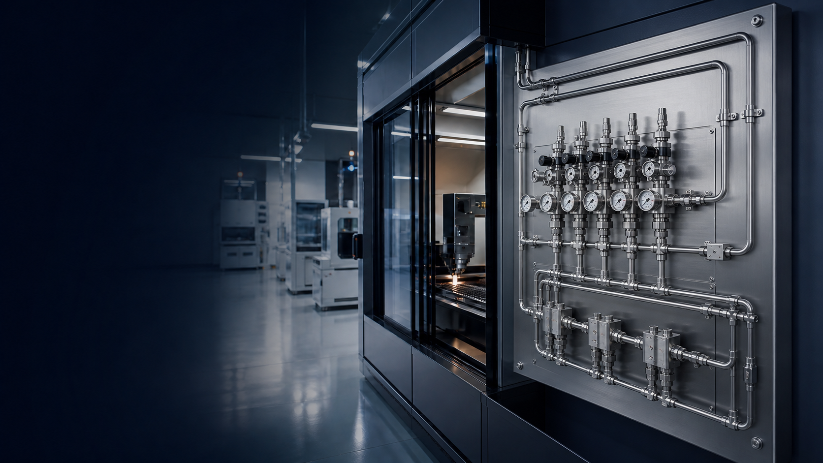
Cylinder grade at the source is not the same as gas condition at the process. Joints, wetted materials, dead legs, regulators, valves and installation practice can add particulate, moisture, oxygen or hydrocarbons, or allow leaks that pull in ambient air.
PES treats the path as a single design: source connection, pressure control, panel functions, distribution tubing, point-of-use isolation and the equipment interface. Purging, leak testing and pressure testing are specified where the duty requires them; they verify the installed system against the project method. They do not, by themselves, create a stated purity class.
Each stage has a defined function. Omit or underspecify one of them and contamination, pressure variation or leak paths show up at the use point even when the cylinder or bulk source is within grade.
Cylinder, bundle, bulk or process supply. Confirm composition, purity grade, residual moisture and hydrocarbon limits with the gas supplier. PES does not assign those values.
Pigtail, hose or tube interface selected for the gas, pressure and connection standard. Wrong materials or dirty hardware at this joint contaminate everything downstream.
Reduces source pressure and, where specified, switches banks. Outlet-pressure variation and wetted-area volume affect both process stability and purge time.
Groups isolation, regulation, indication and, where specified, purge, vent or filtration into one accessible assembly. Layout should limit dead volume and allow isolation for test and maintenance.
Isolation, check, purge and vent valves as required by the P&ID. Seat, packing and body materials must match the gas. Extra valves add joints and trapped volume.
Application-dependent. Used where the duty requires particle, moisture or other contaminant control. Filter rating and location are to be confirmed for the application.
Routed, supported tube or pipe from the panel to use points. Slope, supports, branch tees and accessible joints affect drainability, purge and leak search.
Local isolation, final regulation if specified, and the equipment connection. The last metres still need the same material, joint and purge discipline as the header.
Source connection, isolation, regulation, indication, tubing, fittings and point-of-use isolation are the usual building blocks. Configuration follows the gas, pressures, flow and number of use points.
Changeover manifolds, multi-line panels, filtration or purification, purge and vent circuits, orbital-welded joints, and additional instrumentation are included only when the duty requires them. They are not default on every system.
Tube material, wall, fitting system or weld method, routing and supports are selected together. Mechanical fittings remain serviceable; welded joints reduce fitting count. Neither method replaces leak testing of the finished line.
Allowable outlet-pressure variation, normal and peak flow, and the number of simultaneous use points determine regulator staging and line size. Those values are to be confirmed for the application.
PES cannot size or specify the system from a purity label alone. Send the items below. Missing figures stay marked as to be confirmed for the application rather than assumed.
Composition, mixture, and the supplier purity grade including moisture, oxygen and hydrocarbon limits where they exist. Incompatible elastomers, lubricants or residual oil will add hydrocarbons regardless of cylinder grade.
Inlet pressure, required outlet pressure, allowable pressure variation, normal flow and peak flow. These set regulator type, staging and distribution size.
Number of points, indoor or outdoor location, temperature, vibration and any classified area. These set routing, supports, enclosure and access for purge and leak test.
Preferred tube or pipe material, fitting or weld standard, and thread or tube connection (for example NPT, BSP or tube). Connection standard is to be confirmed for the application.
Applicable site safety requirements, isolation philosophy, and whether leak testing, pressure testing, purge verification and inspection are in the project scope. Acceptance criteria are to be confirmed for the application.
Purging displaces residual process gas, air, moisture and loose particulate from the installed volume. Effectiveness depends on flow path, dead volume, purge gas and procedure. Leak testing locates leak paths. Pressure testing checks containment at the specified test pressure. Inspection records joint condition. None of these steps is a substitute for the others, and none of them states a leak-rate or purity number unless the project specifies one.
Where the specification calls for welded stainless tubing, orbital welding produces a repeatable autogenous joint under controlled machine settings. It reduces the scatter typical of manual welding. It does not by itself remove moisture, particles or hydrocarbons, and it does not replace purge, leak test or visual or other inspection required by the job.
Cut, face, clean and align the tube ends so the weld zone is free of oil, burrs and mismatch. Poor preparation shows up as incomplete fusion or trapped contamination in the bore.
Run the orbital head on the qualified procedure for that tube size, wall and material. Shield gas and purge of the bore, where specified, limit oxidation inside the joint.
Review the weld and adjacent tube as the project requires (visual as a minimum). Reject or repair according to the agreed criterion. Inspection confirms workmanship; it is not a leak test.
Bore condition, residual moisture and particle generation depend on tube specification, handling, storage, end-cap discipline and installation. Surface-finish values, if required, are to be confirmed for the application. PES does not list a default Ra or cleanliness class on this page.
Gas composition and purity grade, inlet and outlet pressure, required flow, allowable pressure variation, number of use points, materials, connection standard, installation environment and applicable safety requirements. Technical enquiries: projects@premaengineeringservices.com. Direct line: +91 9845654261 / +91 80500 00599.
Fields below describe what must be confirmed before design. Numerical purity, leak-rate, surface-finish and pressure values are to be confirmed for the application. They are not listed here.
| Specification | Available Options |
|---|---|
| Gas composition / purity grade | To be confirmed for the application |
| System configuration | Source connection → regulator or changeover manifold → gas panel → valves → filtration or purification where required → tubing distribution → point-of-use control → process equipment |
| Inlet / outlet pressure | To be confirmed for the application |
| Required flow / allowable pressure variation | To be confirmed for the application |
| Number of use points | To be confirmed for the application |
| Materials | To be confirmed for the application (wetted body, seals, tube or pipe) |
| Connection standard | To be confirmed for the application (tube / NPT / BSP or as specified) |
| Filtration / purification / orbital welding | Application-dependent; included only where specified |
| Leak, pressure and purge tests | Method and acceptance criteria to be confirmed for the application |
| Installation environment / safety requirements | To be confirmed for the application |
Related: Gas Panels · Connectors · Gas System Engineering
Share gas type, pressure, flow, points of use and site conditions with the engineering team.